|
Panorama image of my Radio Shack (you can zoom in/out, up/down with your Mouse)
|
|
To search this page simply Hit CNTL F keys to open a find window, then type your search words
Select your Language: |
|
Screen Image received by my friend (running SmartSDR), sent from my PowerSDR v2.8 TXWaterID feature
Pictures of me today and 1991 Field Day
My current Shack layout:
(3) 27" FHD HP monitors
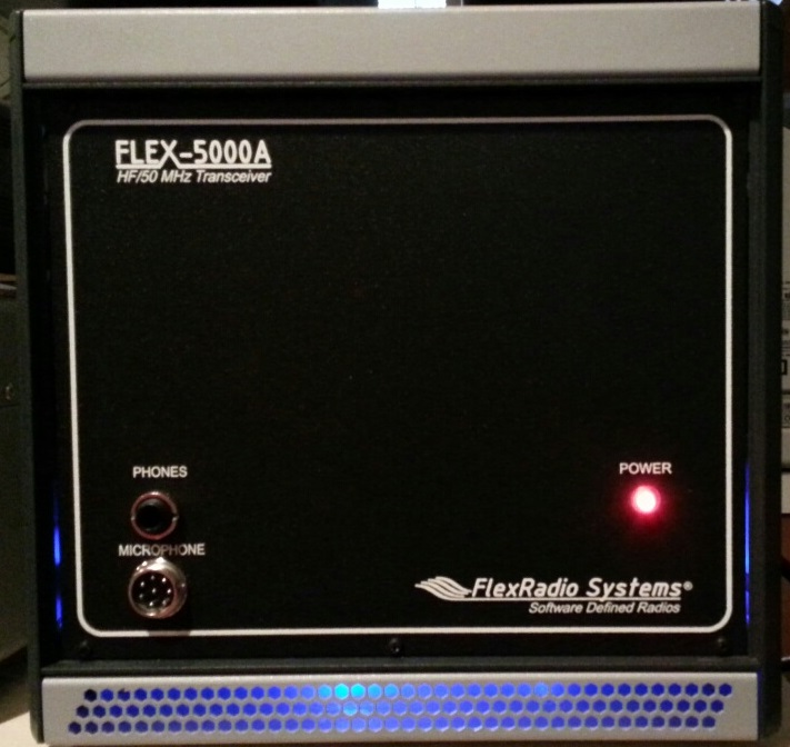
My PC sits behind the Left monitor, My Flex-5000a & Flex-3000 sit behind the center montior.
My audio rack, LP500, antenna rotor, antenna switches and my HW-5400 sits on the shelf.
The Solid-State Amp is behind the Right monitor and the
Ten-Tec Titan 1.5kw Amp over to the far right side.
I now use the audio-technica BPHS1 broadcast stereo headset with Cardioid Dynamic Microphone.
Work bench is to the far Right side.
|
Panorama image of my Radio Shack (you can zoom in/out, up/down with your Mouse)
|
Flex-5000A 100w HF+6m transceiver w/ ATU and RX2 and AM BCB filter (all behind the monitor). Variable RX/TX filters for up to 10k wide
SEE the(FLEX-5000) button at the top of this page

My Homemade Solid-State Amp (click for my page):
Marshall MXL 990 studio mic, Behringer MIC2200 Tube Preamp, Behringer 2496 Ultra-Curve (for EQ, Leveling, Limiting, Gating, and Compression), Behringer EX3200 (for Harmonics), Behringer DSP-1000P Virtualizer Pro (for Plating), and a Ten-Tec Titan 425 amp, and MFJ-998 tuner.
2nd Rig: Heathkit HW-5400100w HF transceiver assembled by myself in 1983 (modded with custom DDS and 2.4/4.0/6.0khz wide RX/TX IF filters for SSB & eSSB operation).
Space Weather - HF Radio Wave Propagation
The Ionosphere layers responsible for HF PropagationLayers are made up of free electrons. These free electrons can act as a mirror to the RF photons from your radio waves. But the density of free electrons and their height determine whether RF photons gets absorbed, refelected, or passes through. Each layers properties is explained below in the following sections.
NM7M Low Band Propagagtion Guide
Checking Propagation based on current Radio contacts and plotting them on a world map (DXMAPS.COM)
Real-Time Sporadic E layer (DXMAPS.com)
Checking Propagation based on Tropospheric Ducting Forecast (dxinfocentre.com)
Space Weather - HF Radio Wave Propagation
The D LAYER (BAD)D (lowest) layer mostly appears with direct Sun (Ultraviolet radiation), but can also occur due to hard X-Ray emissions during a Solar event.
The air density is high at the D layer, but the free electron density is actually low due to high rate of recombination of electrons.
The D layer absorbs RF at the low end (mostly up to 10mhz) of the HF spectrum (high end HF passes through).
So for 10m operation during the daytime, its best to have small D layer and a large F layer.
160m-40m band during the daytime may be absorbed (in part or all) by the D layer
Lower RF Freq. (longer waves) hit more free electrons which in turn hit more air molecules due to air density at low altitudes.
Higher RF freq. is more likely to pass through unharmedLUF (Lowest Usable Freq) means any Freq below this value will be completely absorbed by the D layer.
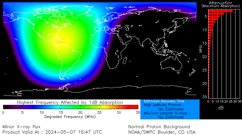
Real-time Global D-Layer Absorption map from NOAA space weather

Space Weather - HF Radio Wave Propagation
The E and F LAYERS (GOOD)E (above D) and F (highest) layers stay in place day and night.
The E layer is formed by soft X-Rays and far Ultraviolet rays
The Sporadic E layer (intense clouds of electrons) can reflect up to VHF frequencies while the normal E layer works up to ~10 mhz
The F layer is formed by extreme Ultraviolet rays. Daytime you get a F1 and F2 layer (highest).
Air density is low so RF energy is re-radiated (reflected) rather than absorbed as in the D layer.
Higher RF frequencies pentrate higher into the E and F layer. A RF freq. too high will simply pass through all the layers into outer space.
RF signals reflected by the F layer will travel further (~2400 miles), then the closer E layer reflected distance(~1200 miles).
Multiple hops are possible.80m-40m take advantage of the E layer, but are strongly affected by the D layer
20m band can take advantage of both E and F layers
15m-10m band take advantage of the F layer
Also, Antenna Take off Angle is very important. Too high and it will not be reflected back to Earth.
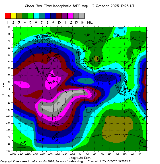
Real-time critical frequency F2 layer map from IPS (Ionospheric Prediction Service)

Space Weather - HF Radio Wave Propagation
A and K Index (Bad)The geomagnetic indices A and K measure the strength of the Earths magnetic field from its baseline (Quiet magnetosphere) level.
So you want low numbers. The higher the indices, the worse the HF bands will be.
The higher the A (0 to 400) or K (0-9) value the greater the disturbance (where free electrons are stirred up) are in the F layers which can reduce MUF by up to 50%
These events usually concentrate closer to the Polar regions (i.e. aurora borealis)
K value is 5 or above constitute an ionospheric storm (major turbulance in the magnetosphere).
The K index is quasi-logarithmic and measured once every 3 hours.
The A index is a linearized scale of the K index.
Space Weather - HF Radio Wave Propagation
Solar Flux Index (Good)
Higher Solar Flux (or higher sun spot #'s) are best (150 to 300). Solar Flux is an indication of ionisation (free electrons) levels.
When combined with low A and K index numbers provides for great HF propagation(GREEN lines) MUF (Maximum Usable Freq). means any Freq above will not be reflected back to Earth
(RED lines ) LUF (Lowest Usable Freq) means any Freq below this value will be completely absorbed by the D layer.
|
|
|
Those Inventors who made it all possible:
