Manuals, Repair, Technical info, Folder locations, Turf/Mars
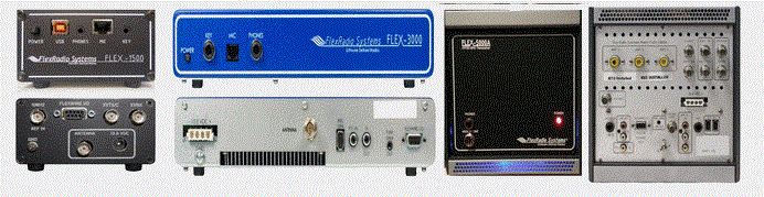
For Flex-1500, Flex-3000, Flex-5000
See the very end for TURF and MARS info.
Click on images (below) to enlarge
Use the manuals below at your own risk!
click to download KE9NS Flex-5000 Radio Owners Manual v2.8
Note: You can use most
of the features listed in this manual in both the Flex-1500 and 3000 as well.
-------------------------------------------------------------------------------------------------------------------------
If your having 60m Band issues
The TURF Region set for your Flex Radio will determine if 60m is available for Transmit. Your Radios TURF region appears on the top line of the PowerSDR console screen.
Your Radios TURF region can be changed from within PowerSDR v2.8
If after you have updated PowerSDR to 2.8.0 and your Flex Radio is Turfed to "Europe" or some area that now has 60m Transmit
but you have trouble transmitting, you can download a text file containing an example of
values you should find in your Radio's Database file.
Click on the button for your radio: Flex-1500, Flex-3000, Flex-5000
These are the 60m calibration
from my Flex radios.
You can search your radio's database file (folder: %userprofile%\AppData\Roaming\FlexRadio Systems\PowerSDR v2.8.0\)
Open up your database file: database_RevQ_F5K_1234-5678.xml (but with your serial number)
and see if any of these
are missing or corrupted as compared to my database (found in 1 of the 3 files above).
If your 60m values appear to be missing or incorrect, use the calibration values from my text file to modify your database file.
Now if you are satisfied that you have modified your database file values, and didn't mess anything up,
you can save these new 60m values to the Flex-1500 EEPROM by opening up PowerSDR and hitting SHIFT + CTRL + C keys
Then click on the "Save Calibration values to EEPROM" to update your Flex radio using your current database file as the source.
(WARNING: You could make things worse if your database file calibration is not correct and you perform the step above.)
-------------------------------------------------------------------------------------------------------------------------
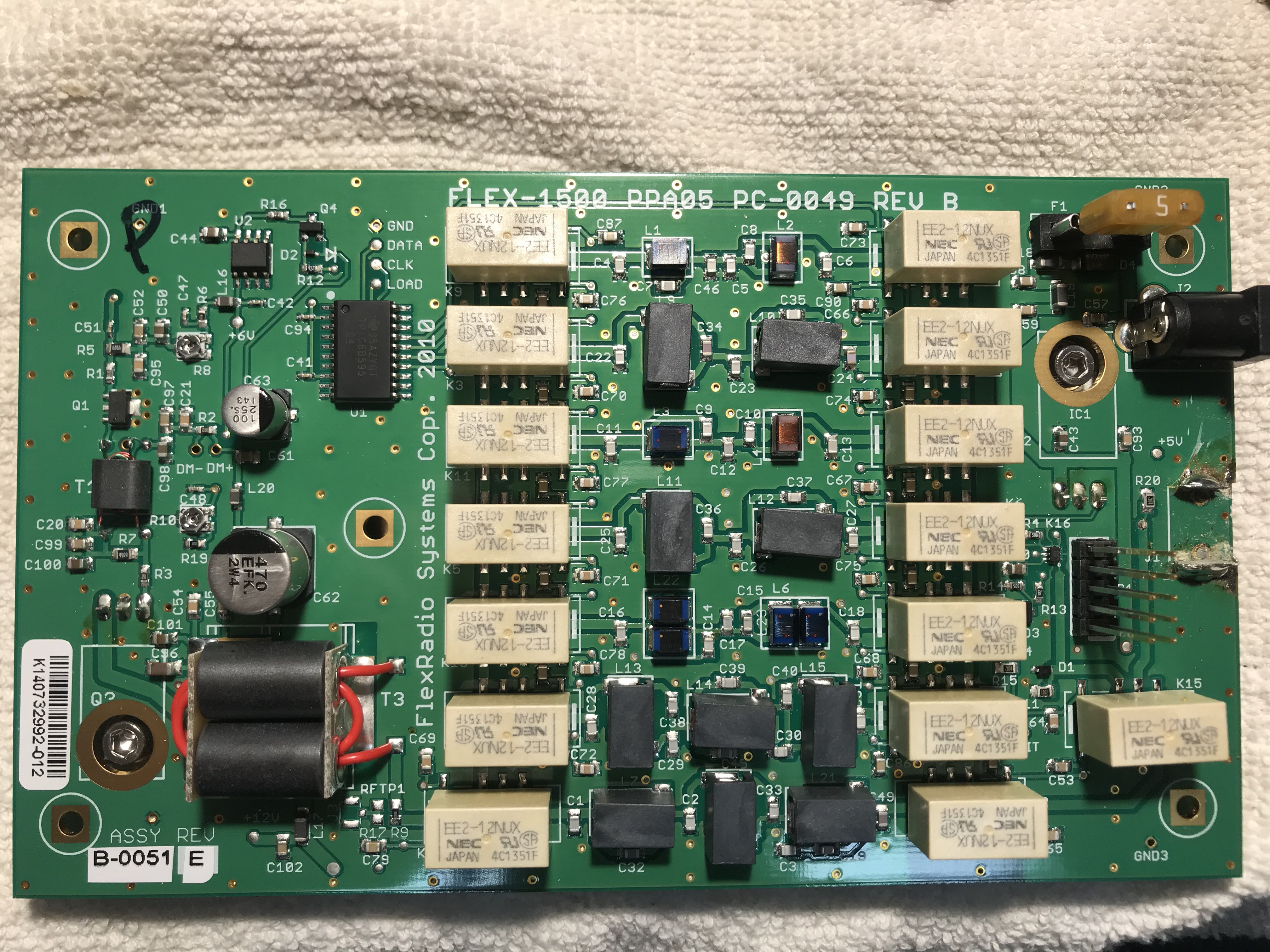
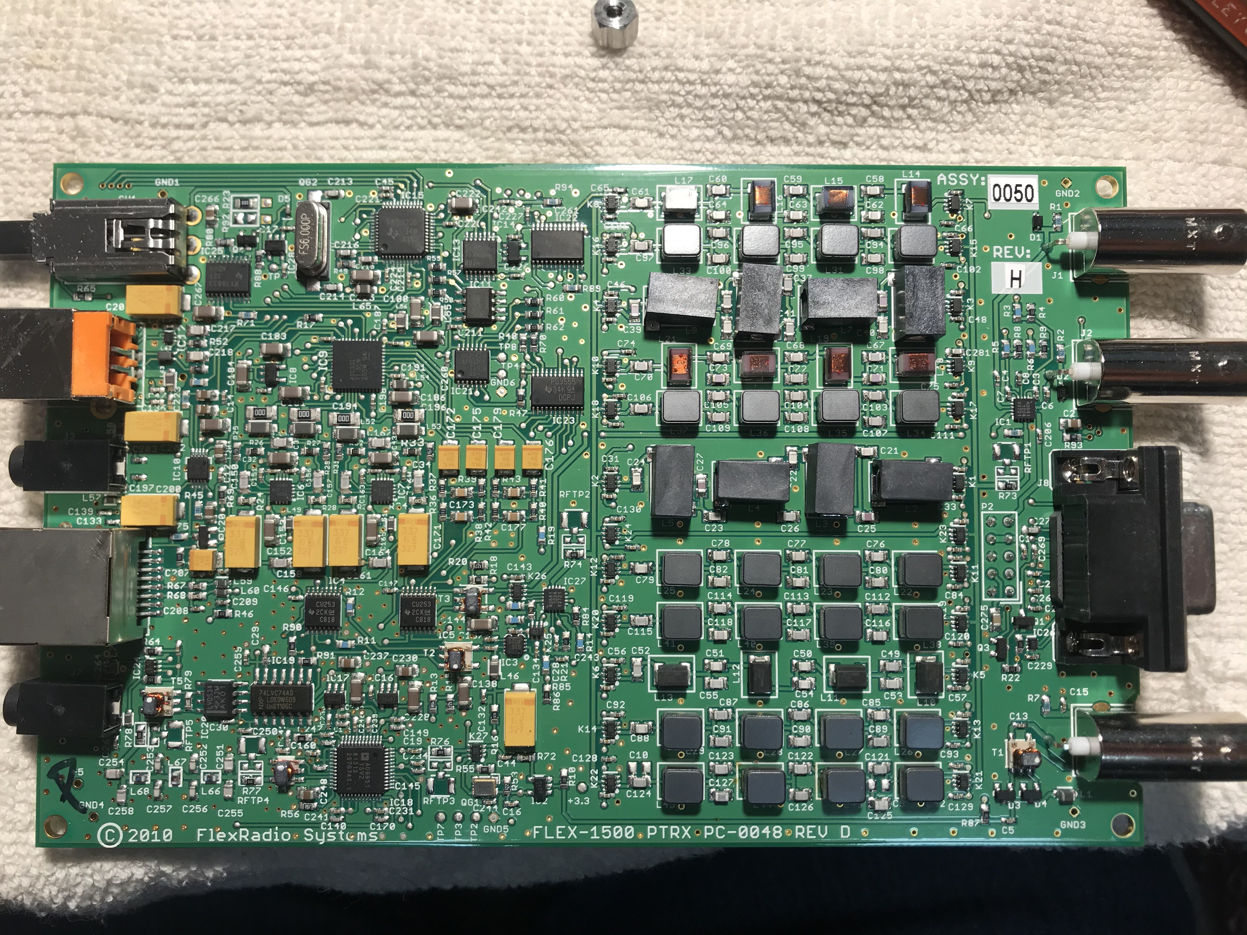
Flex-1500 section
click to download FLEX-1500_Owners_Manual_v2.0
click to download FLEX-1500 Service Manual
-------------------------------------------------------------------------------------------------------------------------
Flex-3000 section
Click to download FLEX-3000_Owners_Manual_v2.0
Click to download Flex-3000 NPA schematic
Click to download Flex-3000 NTRX schematic
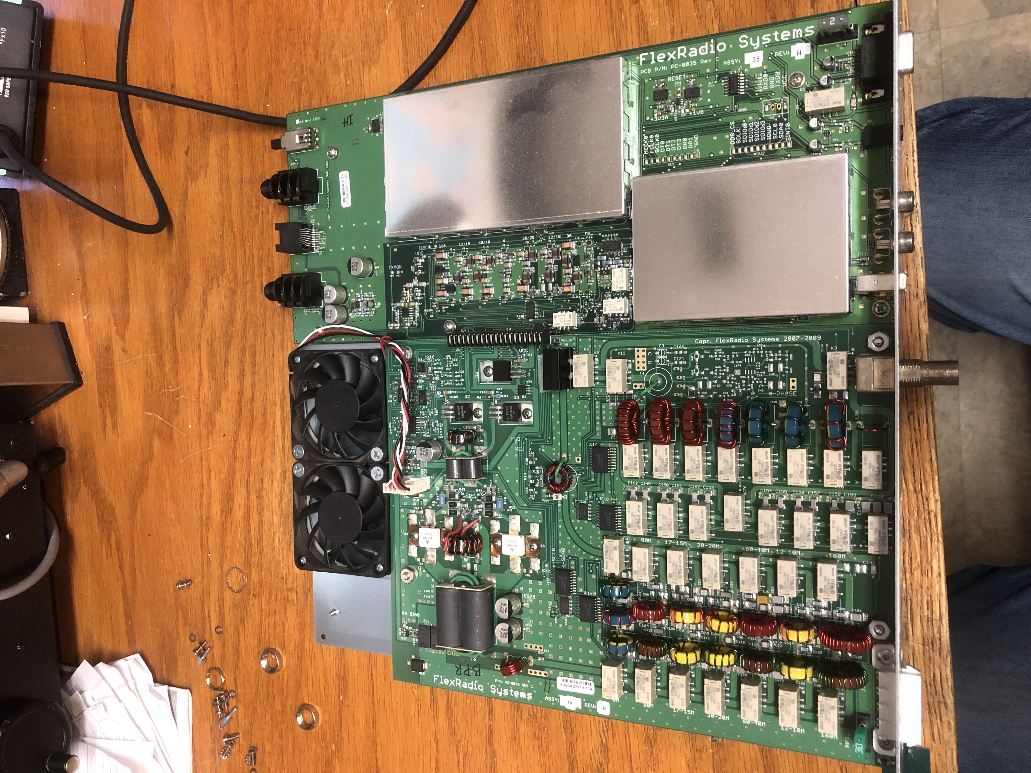
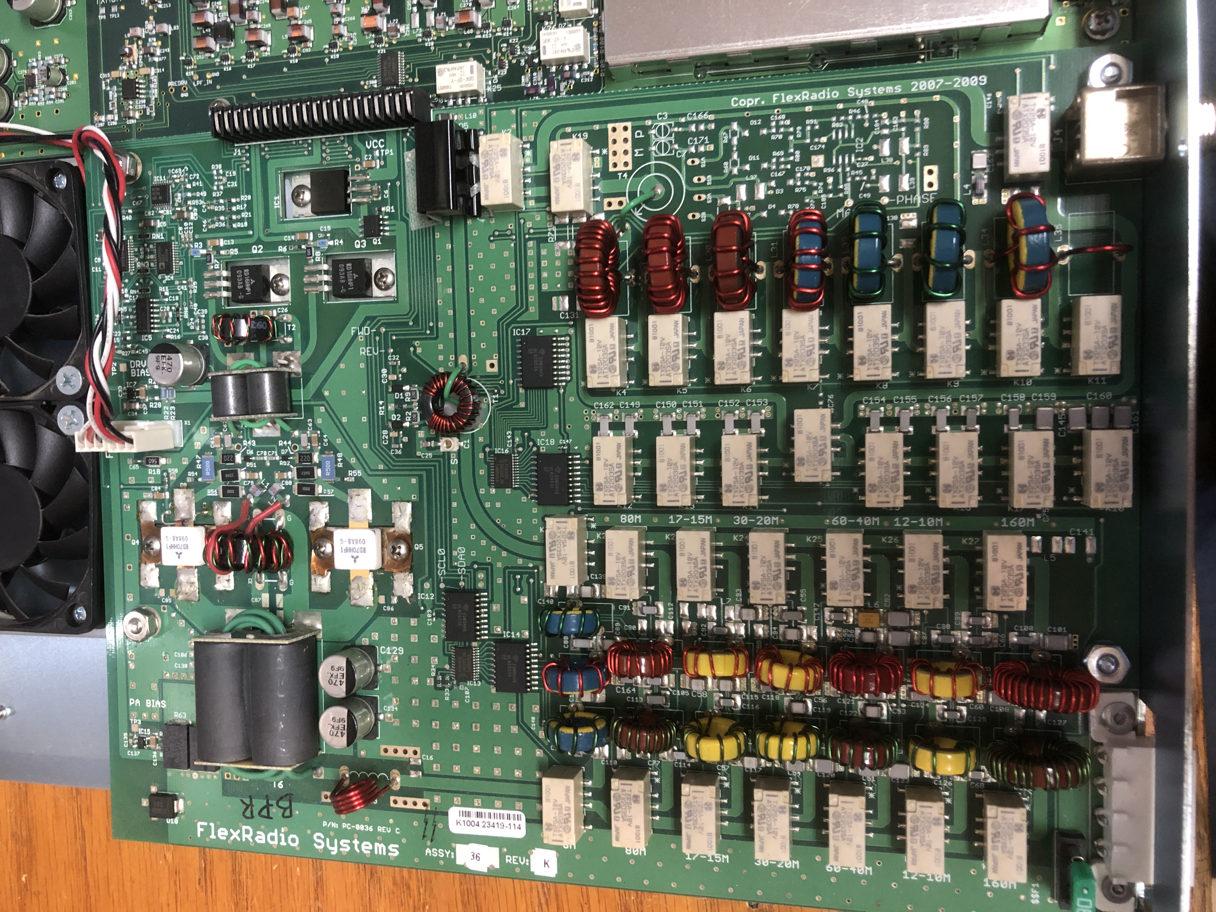
Overall photos of the Flex-3000 PCB
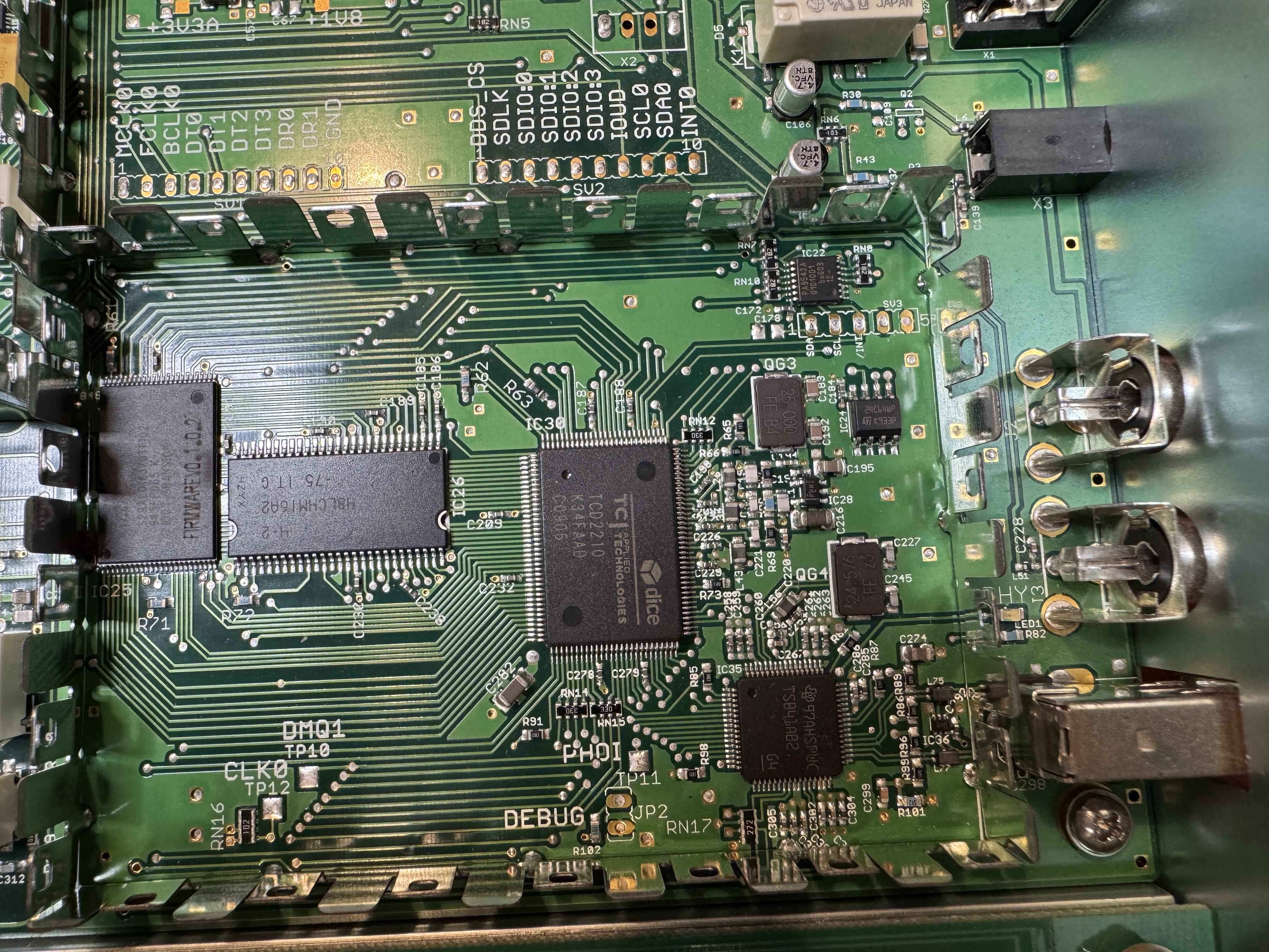
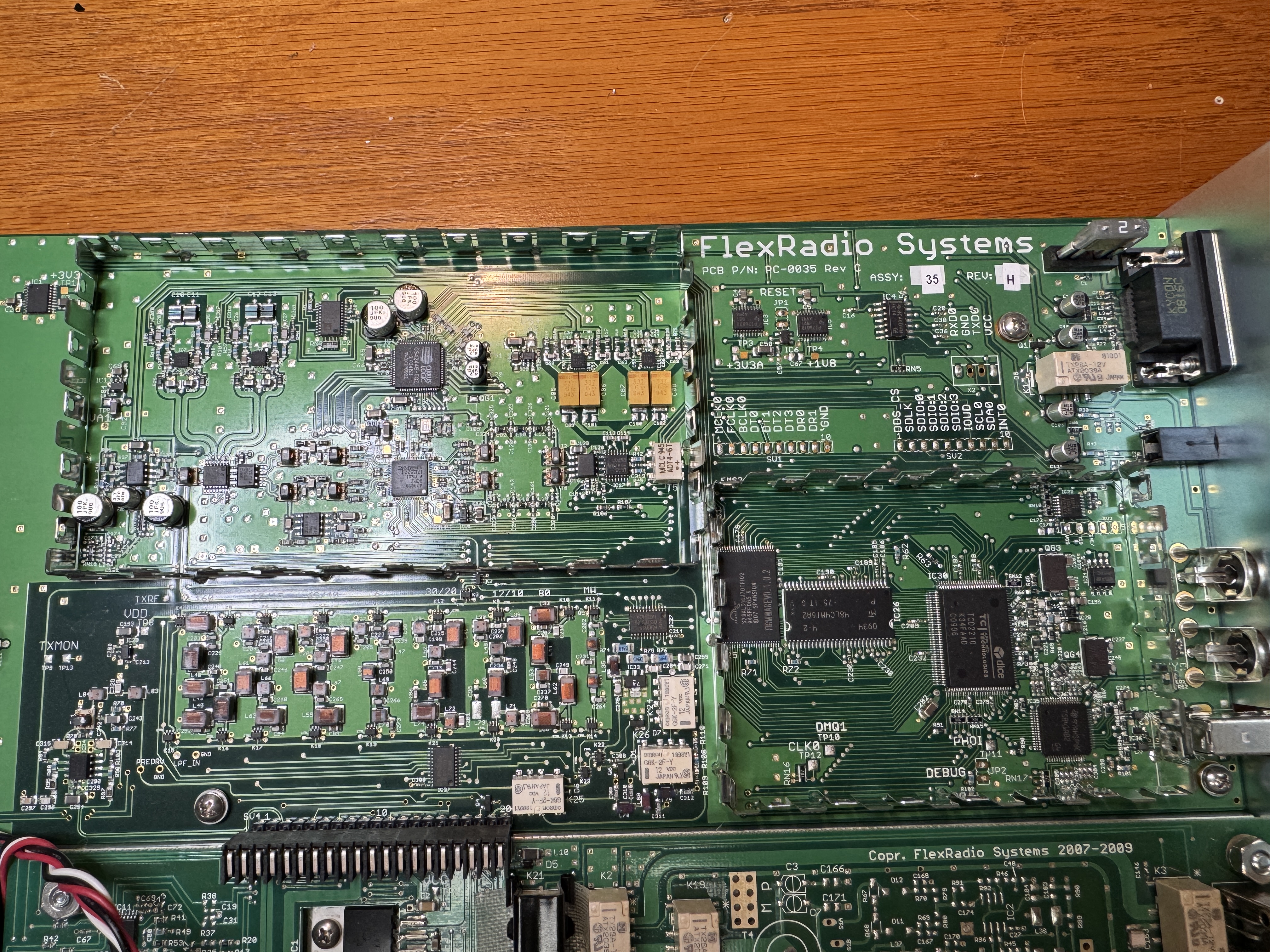
Left: Flex-3000 FireWire section Close-Up, Right: Flex-3000 FireWire, CPU, RX/TX LPF & BPFs
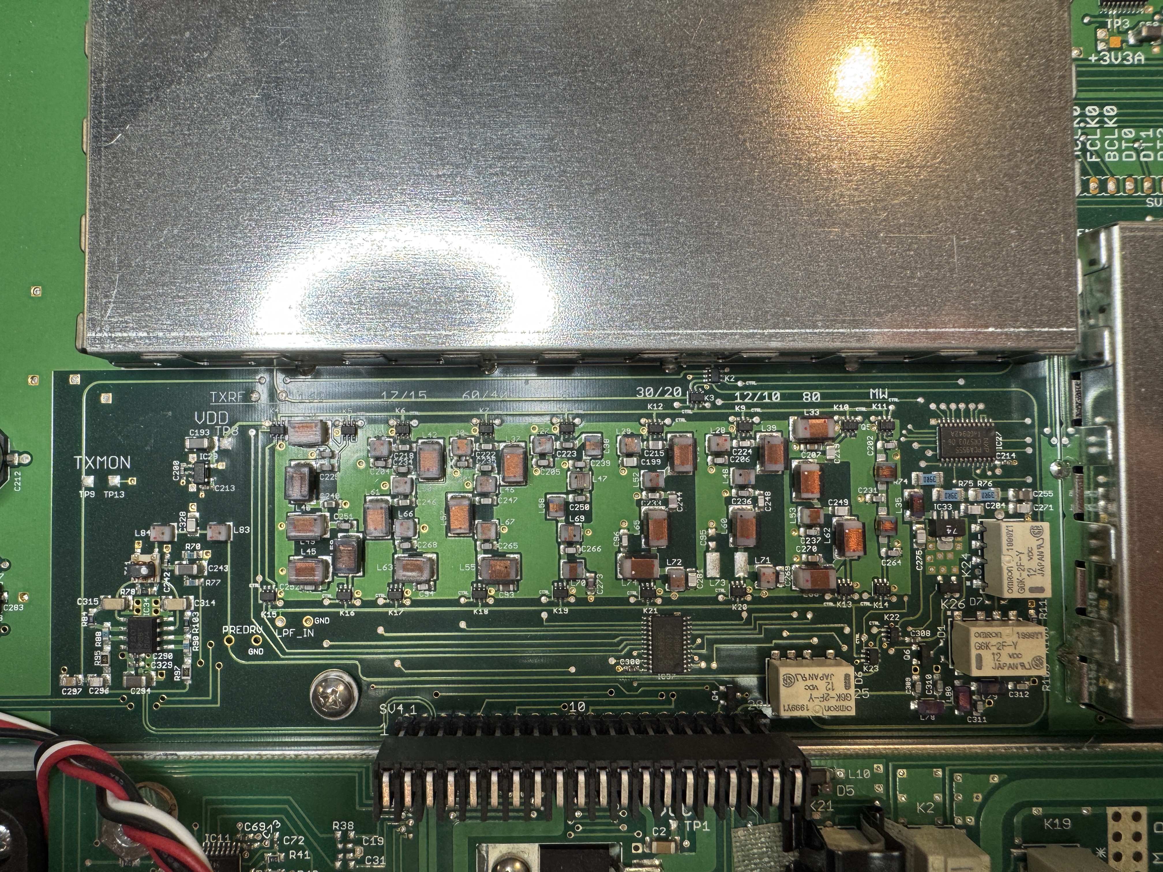
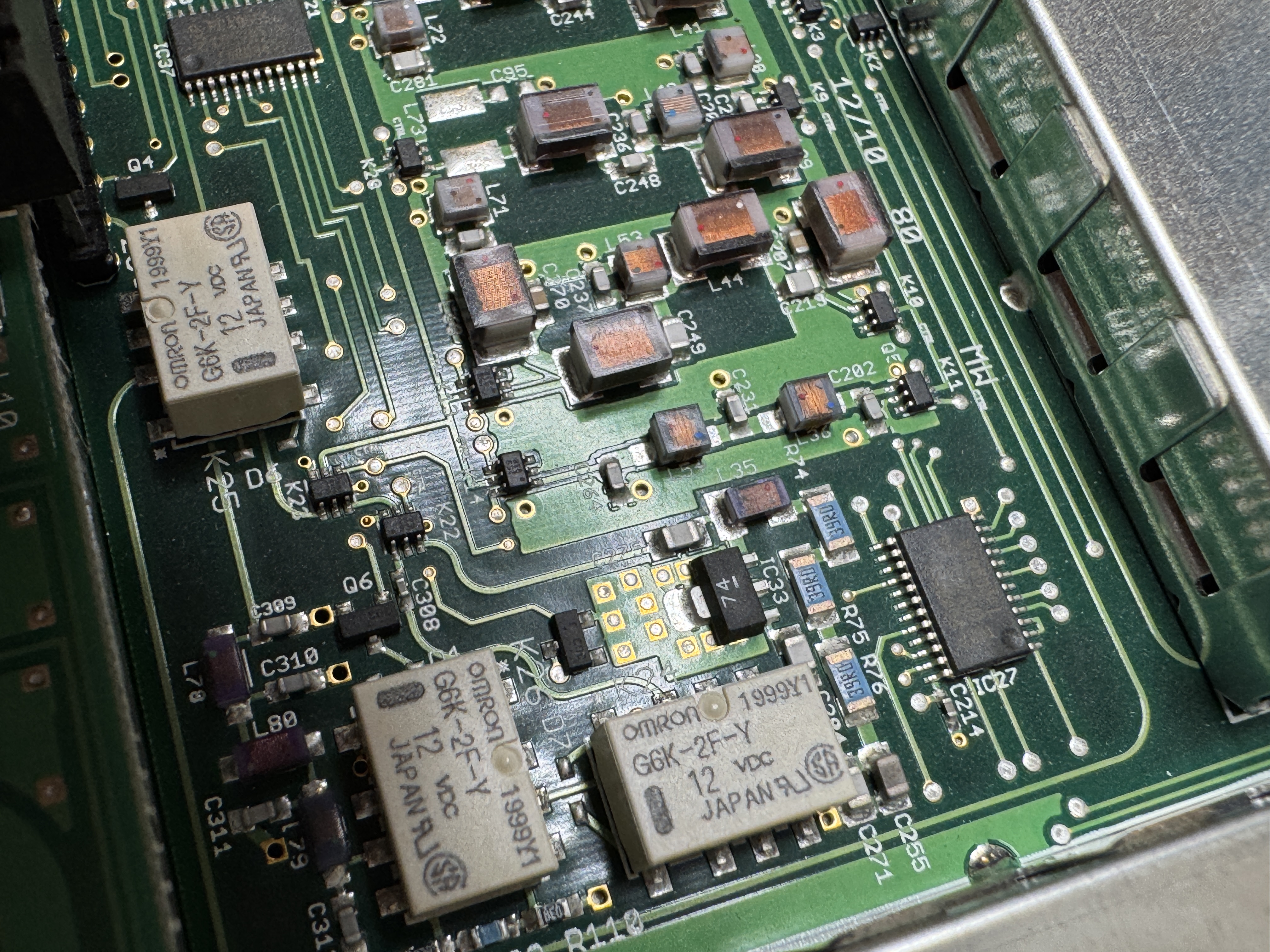
Left: Flex-3000 Close-Up of RX/TX BPF & LPF section, Right: Flex-3000 Close-Up MW LPF (RX/TX)
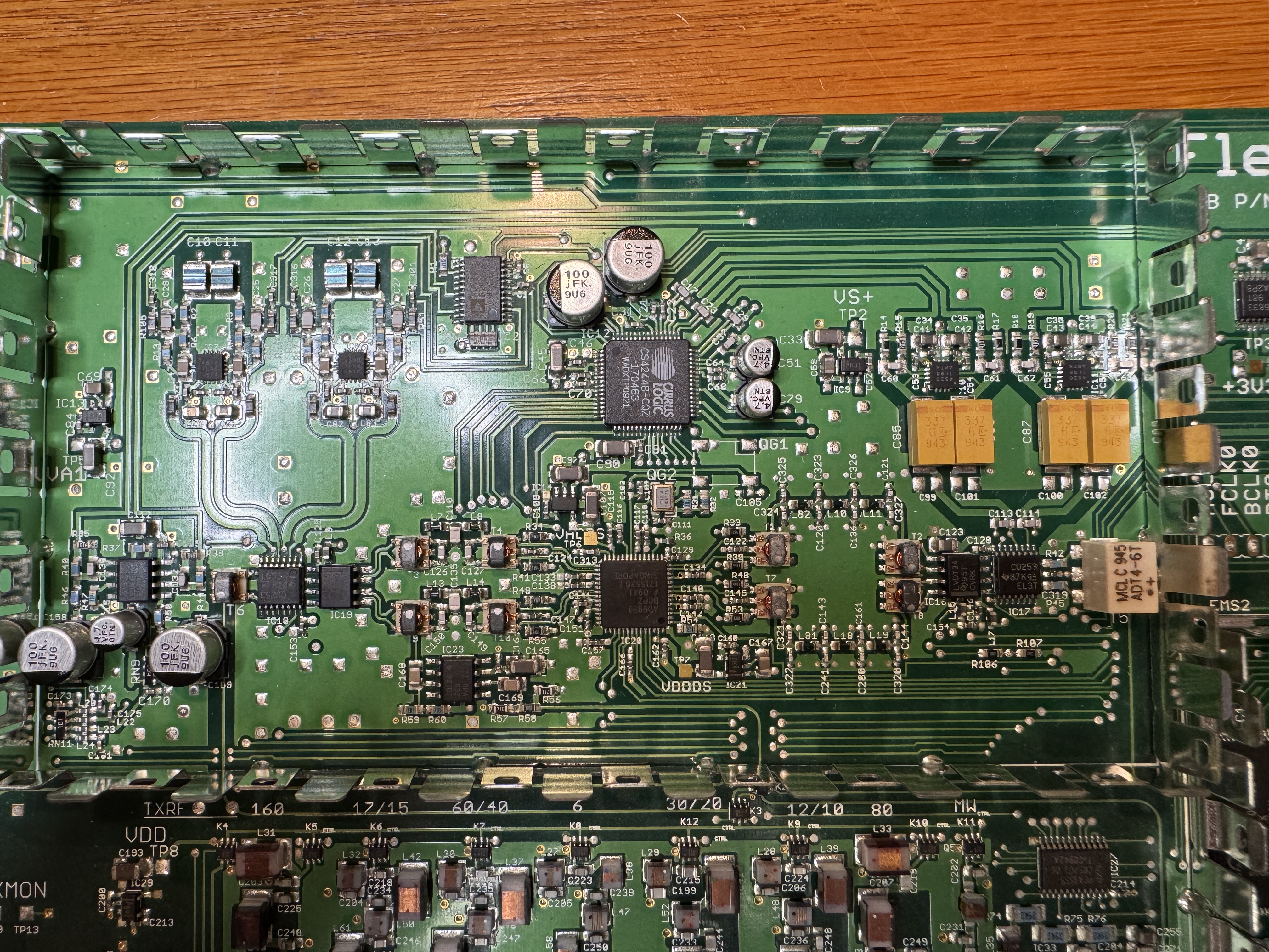
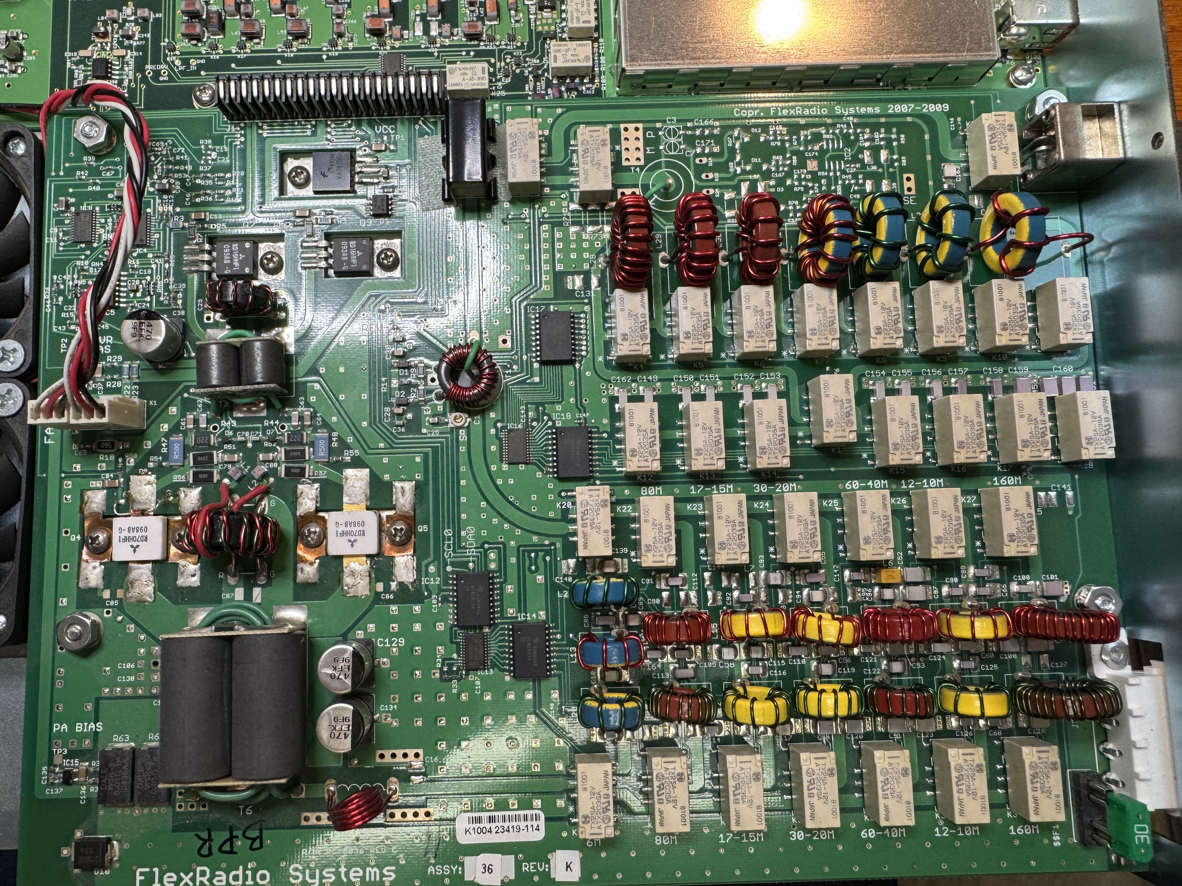
Left: Flex-3000 Close-Up CPU section, Right: Close-Up PA, filter, ATU board
Bringing a Flex-3000 back from the dead:
Flex-3000 EEPROM replacement PDF (by Michael - DL2FW)
I would think that this should work for the Flex-5000as well.
NOTE: Flex-3000 puts out full power on 630m (but you must use an external 630m LPF capable of RX and 100watts TX)
-------------------------------------------------------------------------------------------------------------------------
Flex-5000 section
click to download FLEX-5000_Owners_Manual_v2.8
click to download my ke9ns Flex-5000 database file.
If you setup->import this database file it will start you off exactly as I have my Flex-5000 setup. Your Flex-5000 will automatically download its own EEPROM calibrations (replacing my Flex-5000 calibrations) as soon as you import my file. NOTE: I use the balanced Mic input on the back of the radio.
click to download FireWire connection check EEPROM tool instructions
click to download FLEX-5000 ATU-100 Service Manual
click to download FLEX-5000 ATU Installation Guide
The above instal guide is only for the 52B
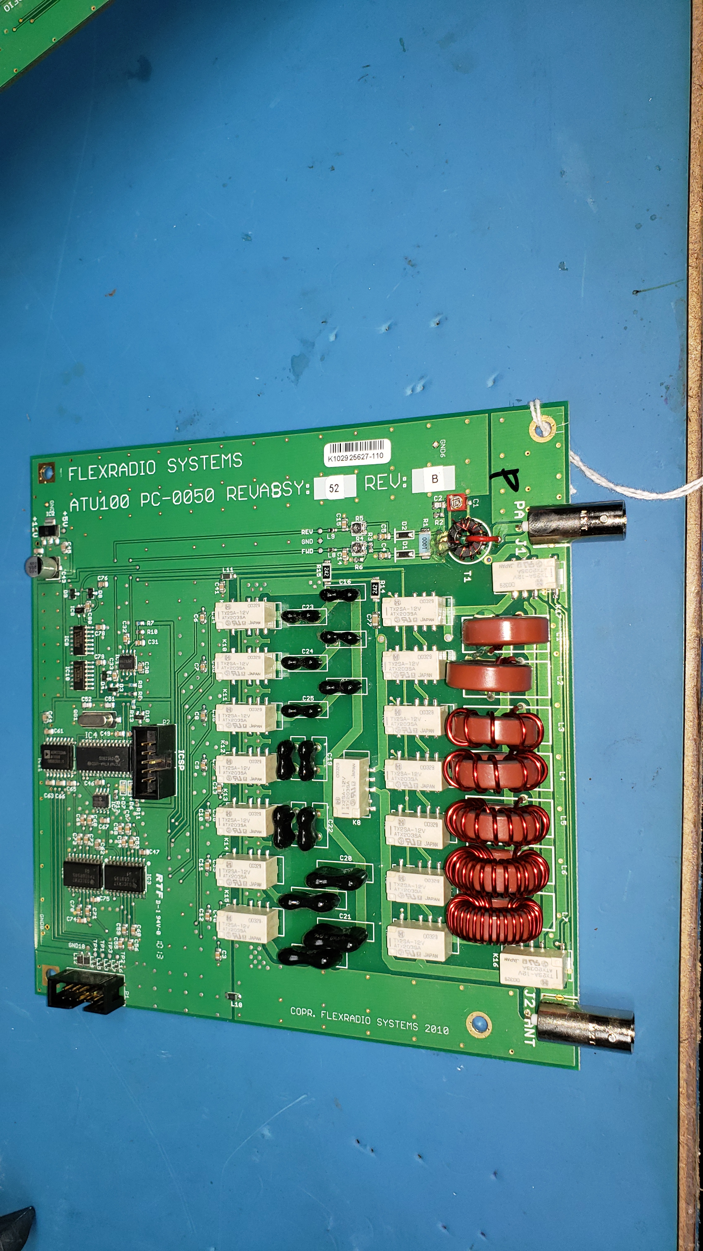
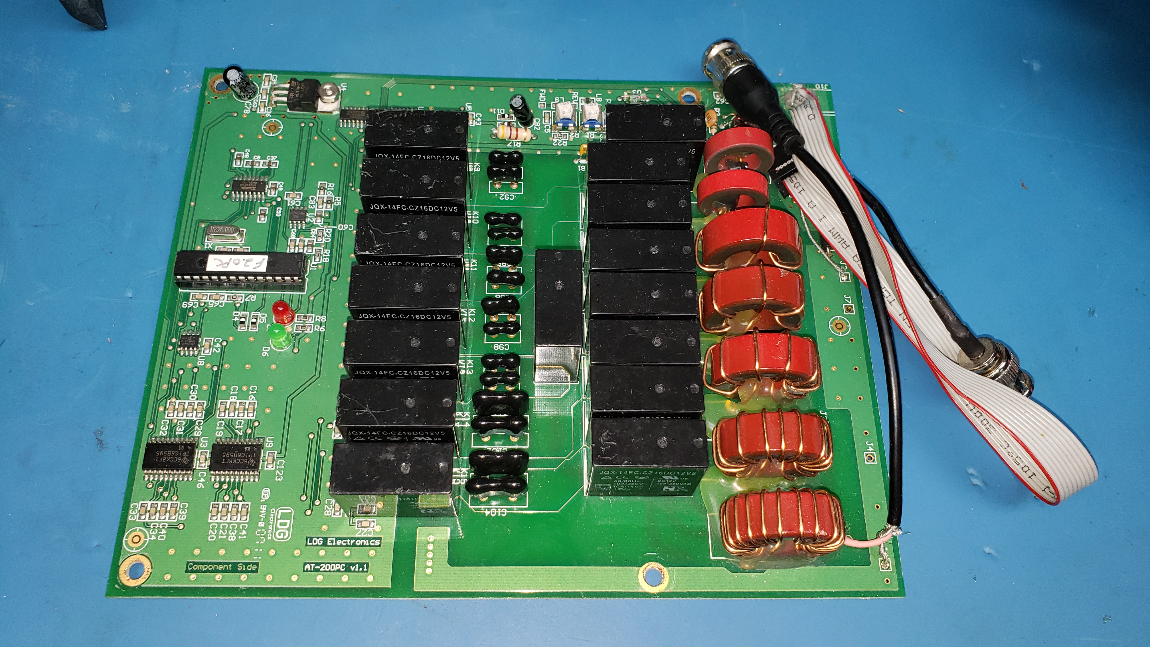
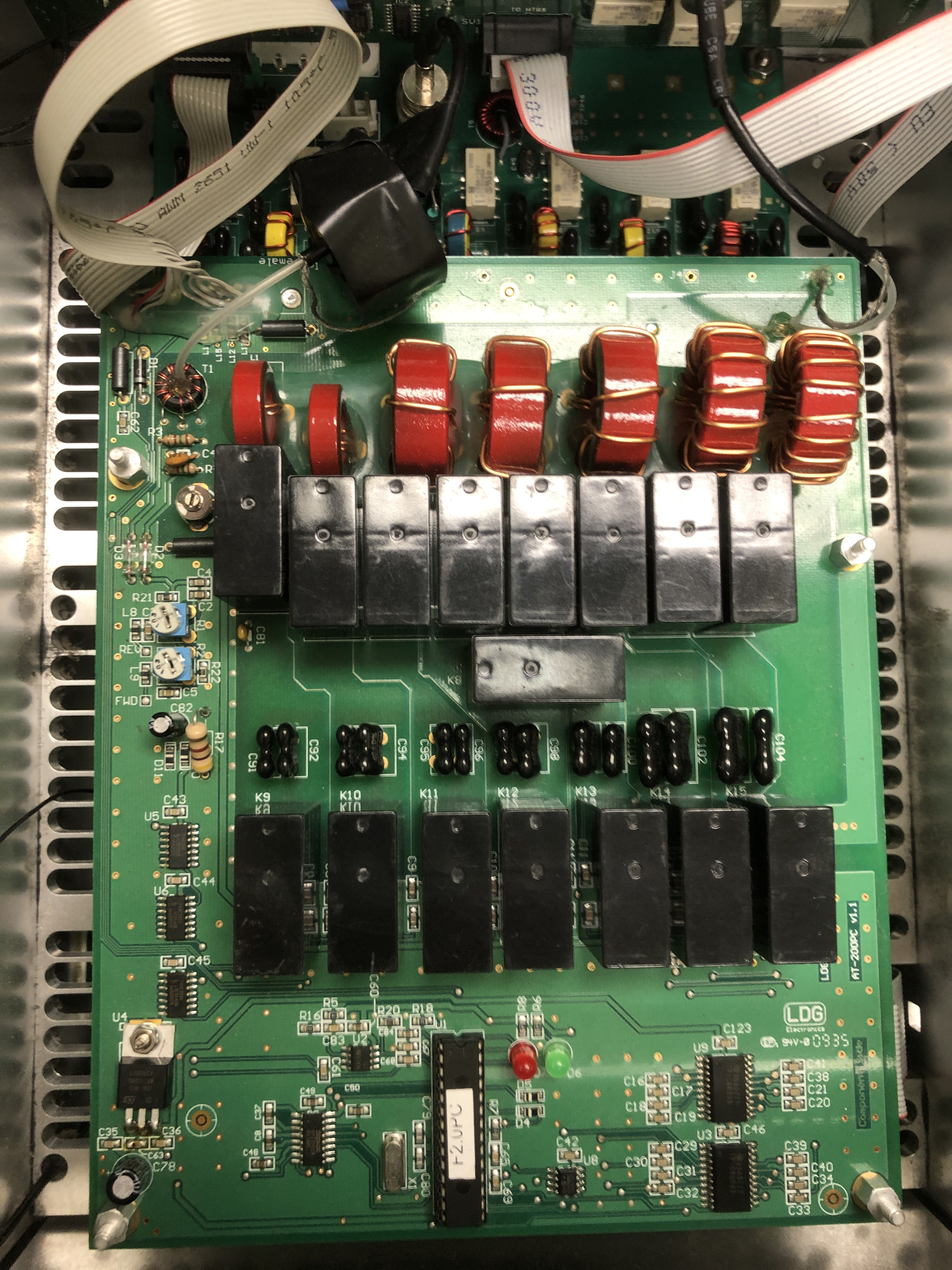
ATU-100 pc-0050 (52B) ---and---- ATU-200pc v1.1(LDG)
click to download FLEX-5000 Service Manual
Flex-5000 with 2nd Receiver and VU5K option (below)
(Note the extra cabling and boards, and the engineering change to 160m and 80m LPF)


Flex-5000 with 2nd Receiver but no vu5k (below)
(Note the engineering change for the 160m LPF)
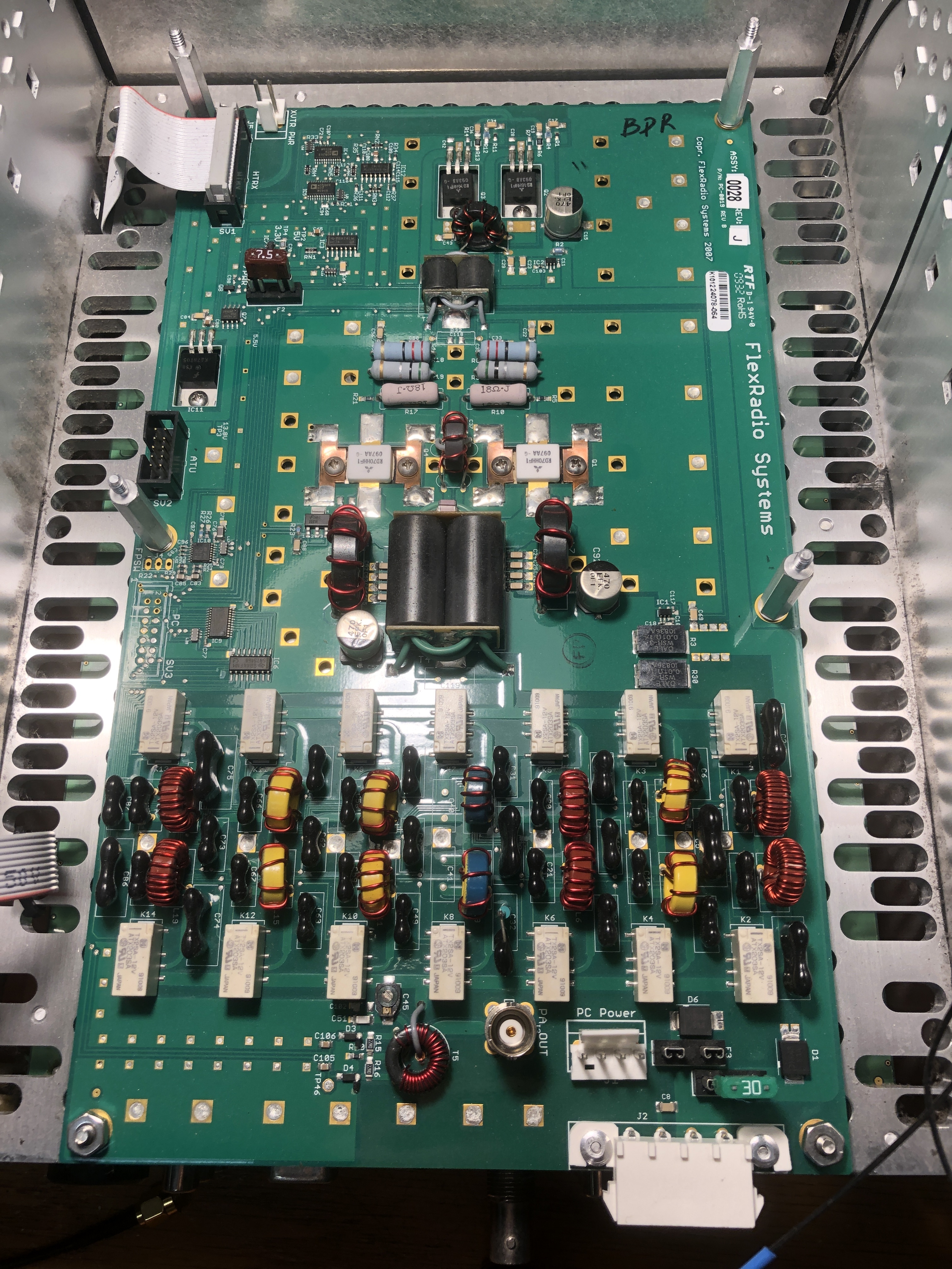
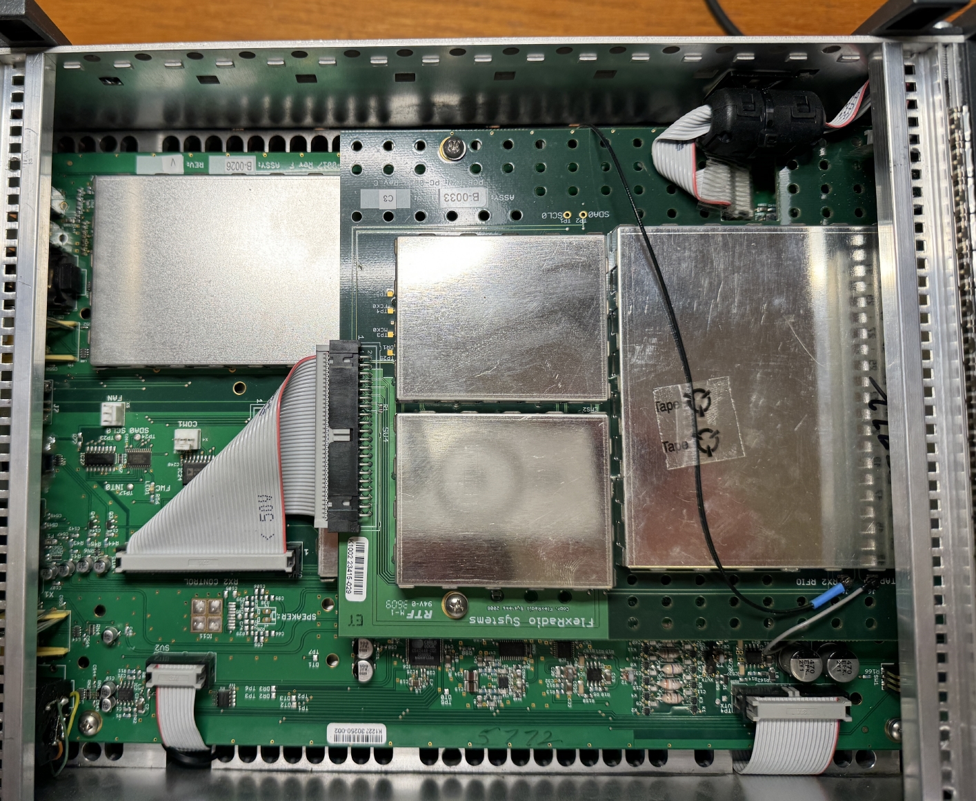
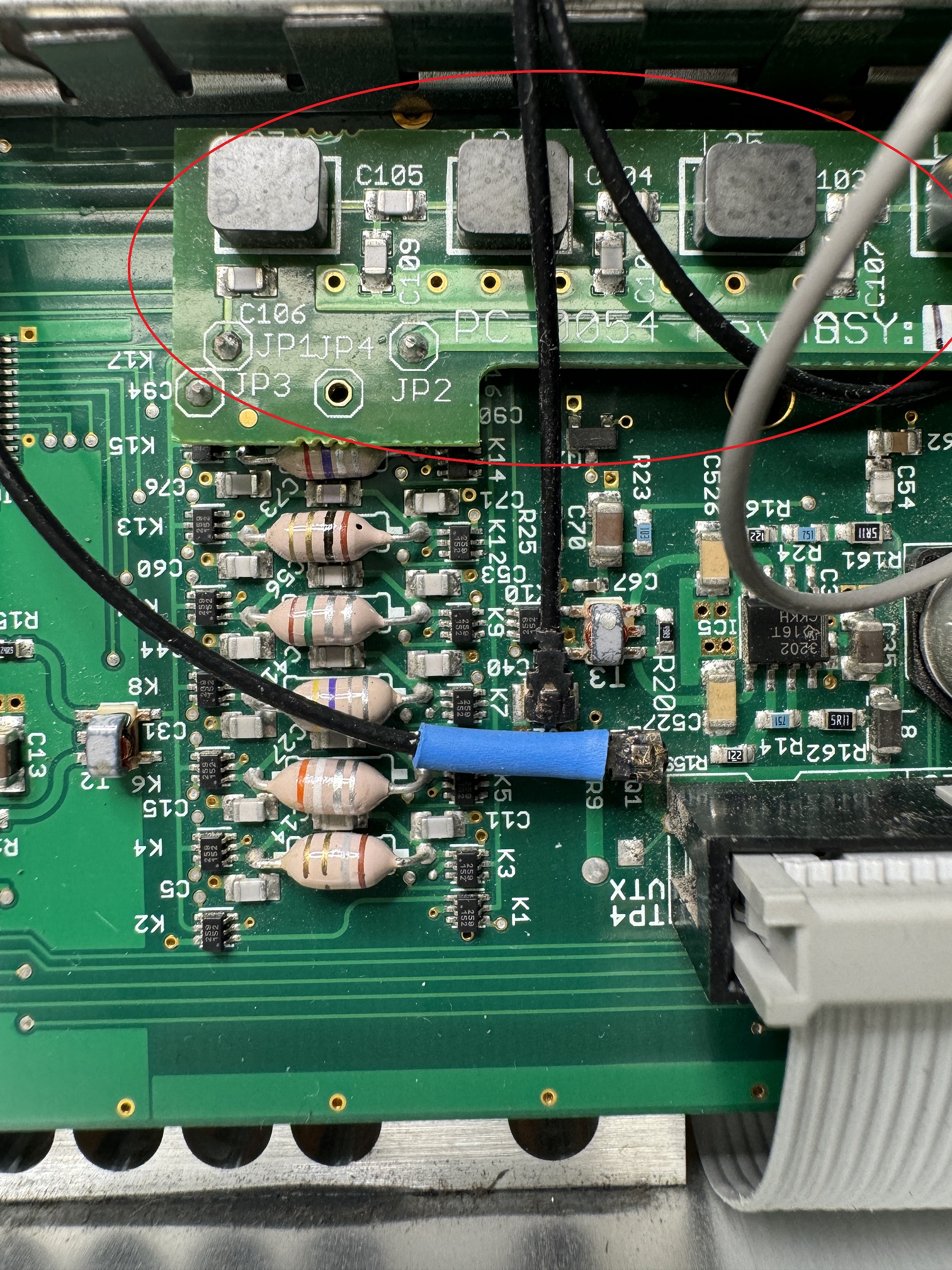
(Left) HPA100 PC-0019RevB Assy 28
(Center)
Main HTRX with 2nd Receiver module stacked above.
(Right) PC-0054 160m 7 pole LC BPF board on HTRX board installed (This ECO was to reduce spurs from the original 4 pole 160m PI LPF, but this prevents 630m operation on a Flex-5000)
NOTE: All Flex-3000 units can transmit on 630m (100watts) because the Flex-3000 uses a MW LPF (Flex-5000 does not have a MW filter) which the Flex-5000 originally just used the 160m LPF, but and ECO changed 160m to a BPF which blocks anything below 160m
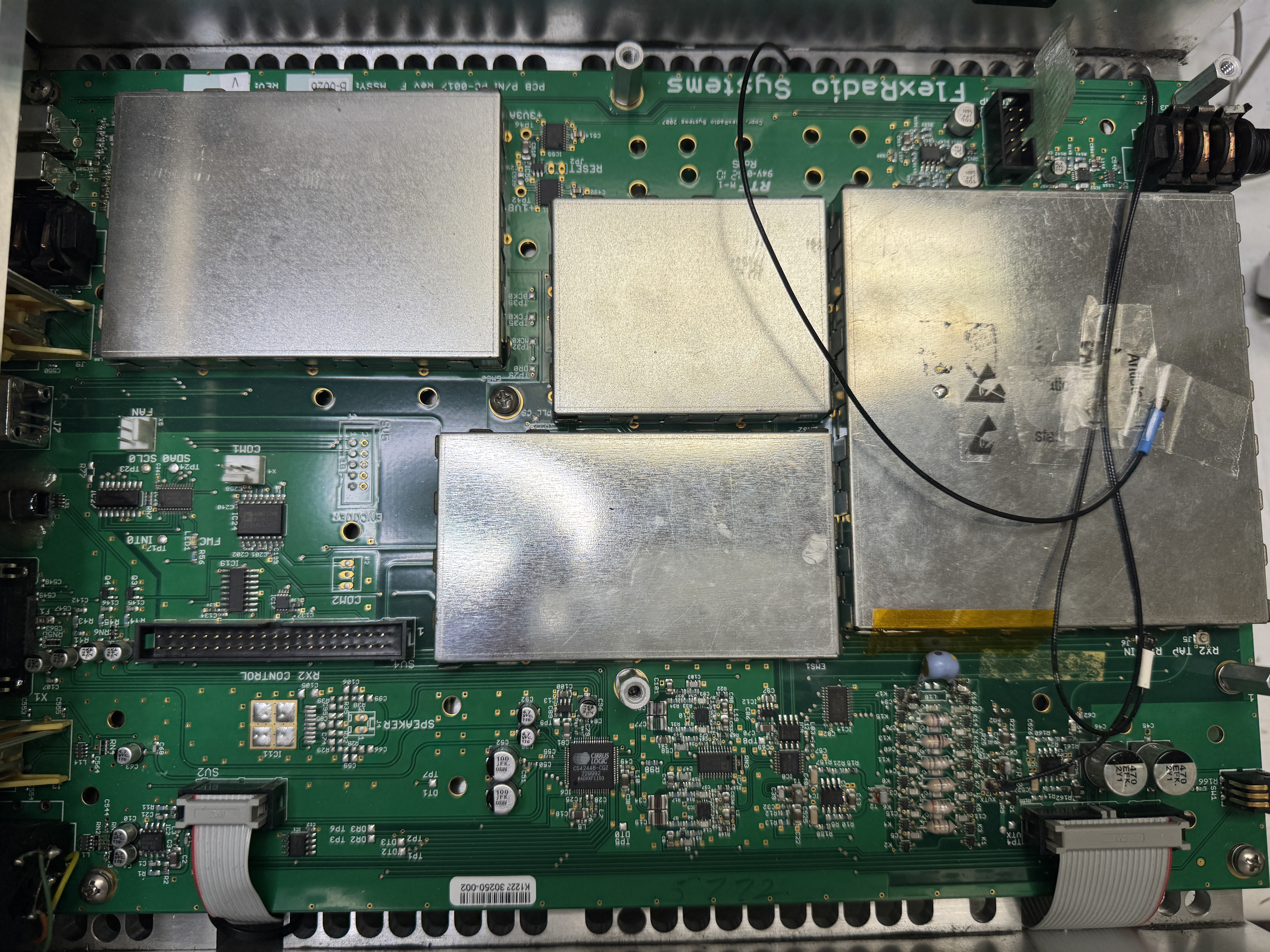
Flex-5000 HTRX board (2nd RX board removed). Put back a 160m LPF to allow using 630m band.
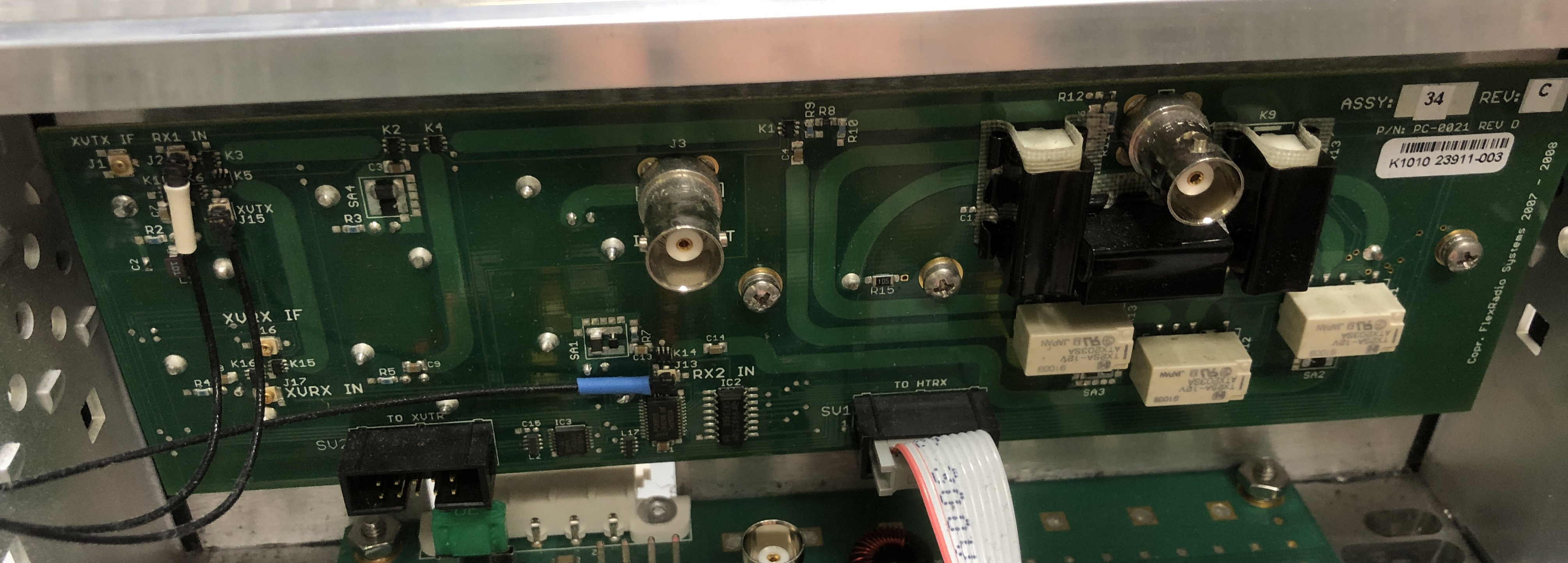
HRFIO SO2R PC-0021Rev D Assy 34
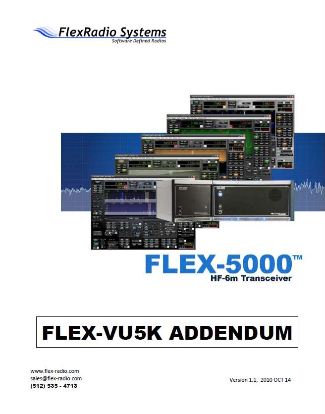
Click to download VU5K module Addendum
click to download FLEX-5000 VU Module Schematics
click to download FLEX-5000 RFIO Rev34A install guide
click to download FLEX-5000A Specifications
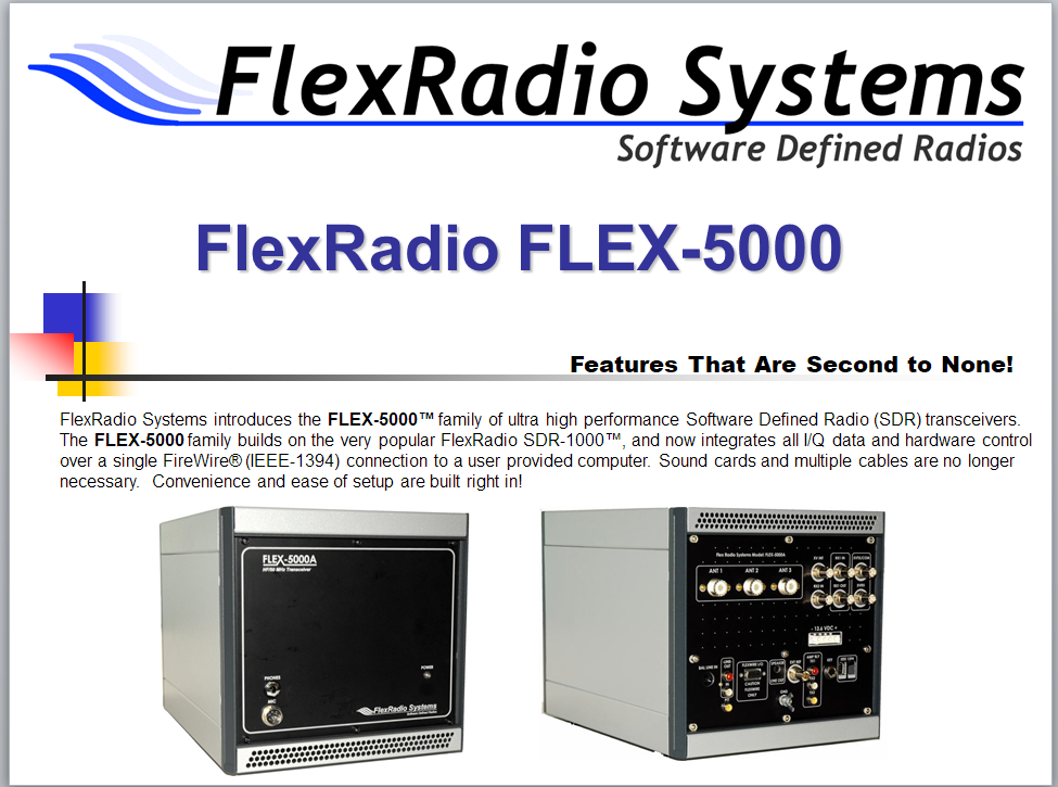
Click to download Flex-5000 PowerPoint Information
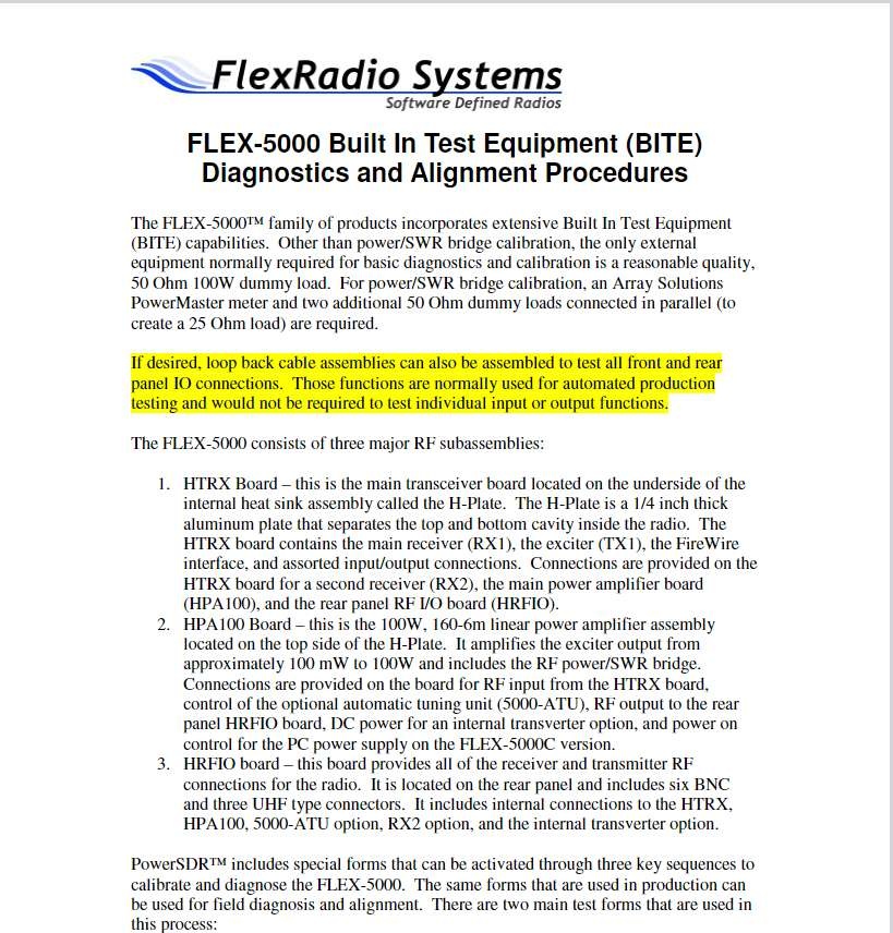
Click to download (Premliminary) Flex-5000 BITE Alignment & Diagnostics
This includes the hidden Production TRX /IO Test and Calibration screen
Flex 5000A Running Class A and Bias Adjustment
Flex-5000 TX_audio_stages
Flex-5000 old firmware_1.3.0.8.exe (if needed upgrade a very old unit)
Flex-5000 fan: 140mm (3-wire) PC fan:


-------------------------------------------------------------------------------------------------------------------------
SWR meter reading issue on the Flex-5000:
(Note the Flex-3000 has 1 SWR circuit so avoids issues, and the Flex-1500 does not have an SWR circuit built-in.)
The Flex-5000 has a built in SWR meter. Its circuit is located on the PA board and is electronically calibrated at the factory (using Powermaster external meter), and its SWR is displayed on the main PowerSDR screen TX meters.
But if you have the internal Tuner, the Tuner itself has its own SWR meter (see ATU photos above and look for T1). Its calibrated using the C1 vari-cap.
There is a small amount of coax between the 2 SWR meters inside the radio. The built-in Tuner uses its own SWR meter during the "ATU" tune process.
So depending on your antenna (i.e. how far from resonance) you may find the SWR meters read differently (with each piece of coax causing the SWR to be different at different locations along the coax.
And most likely any external SWR meter will read a different SWR since its even further before the tuner.
The SWR across the meters should be very close when running a resonant antenna, so if you find a large difference in this case, you may want to tweak the C1 vari-cap of the internal Tuner.
The internal Tuner SWR circuit (T1) has a vari-cap adjustment C1. That vari-cap may need a slight adjustment to get the built-in SWR meter to match.
The Tuner is either built by Flex or LDG (my unit was an LDG) but there is only 1 vari-cap (C1) to adjust.
-------------------------------------------------------------------------------------------------------------------------
click to download PowerSDR-CAT-Command-Reference-Guide
click to download PowerSDR ke9ns keyboard shortcuts
Flex-x000 EEPROM PROGRAMMER_2.1.0.0_(must be located in folder with PowerSDR itself
------------------------------------------------------------------------------------------------------------------------------------------------
Folders used by PowerSDR:
C:\Program Files (x86)\FlexRadio Systems\PowerSDR v2.8.0
------------------------------------------------------------------------------------------------
PowerSDR.exe itself
EEPROM.exe (for exporting / importing EEPROM data and reading/writing Radio data)
Turf.txt
LoTW_help.rtf
CATStructs.xml
C:\Program Files (x86)\FlexRadio Systems\PowerSDR\Documentation:
------------------------------------------------------------------------------------------------
Owners_manual v2.8
PowerSDR TX Waterfall ID pdf
FlexControl quck start guide
VU5K manual addendume v1.1
C:\Program Files\FlexRadio
-----------------------------------------------------
FlexRadio.exe (Firewire) program
C:\ProgramData\FlexRadio Systems\FLEX Firmware\:
---------------------------------------------------------------------------------------
NOTE: PowerSDR normally automatically updates your radios firmware to the lastest
Tool.exe (manual firmware update tool)
Flex-1500 firmware folder
Flex-3000 firmware folder
Flex-5000 firmware folder
FlexControl firmware folder
C:\ProgramData\FlexRadio Systems\PowerSDR\:
---------------------------------------------------------------------------------
FireWire Driver installer folder
Flex-1500 Driver installer folder
FlexControl Knob installer folder
Skins folder (sub folders containing skins)
powermaster.txt (calibration data for flex5000finaltestform)
Note: In WinXP C:\Documents and Settings\ became C:\ProgramData\ in WinVista. But PowerSDR ke9ns v2.8 will not work under WinXP or Vista
%userprofile%\Music\PowerSDR
---------------------------------------------------------
"Wave" audio recordings (not the QuickAudio) (in WAV format only)
"Memory" audio Recordings (in MP3 format only)
%userprofile%\AppData\Roaming\FlexRadio Systems\
-------------------------------------------------------------------------------------
master.xml (powerSDR startup radio selector screen)
production (empty file needed if you want to calibrate the PA)
memory.xml (memory listing)
ATUdatabase.xml file (Flex-3000)
ATU.log file
DXMemory.xml (DX Spotter URL listings)
%userprofile%\AppData\Roaming\FlexRadio Systems\PowerSDR v2.8.0\:
------------------------------------------------------------------------------------------------
Database files (5) (example: database_RevQ_F5K_1211-3170.xml)
QuickAudio folder (standard large wav file recordings)
QuckAudioMP3 folder (MP3 files of all quick audio recordings)
QuckScreen (screen shot. click on camera) folder
SWR_PLOTS folder (see Scanner)
CustomScannerList folder (see Scanner)
TXWaterFall ID (BMP) image files
.log files (shutdown logs, error logs, atu log)
LoTW_LOG files (your log files) (see Spotter)
SWL.csv file and SWL2.csv (short wave listings)
FCCDATA.dat file (call sign database file) (see Spotter)
DXLOC.txt (country name and location listing) (see Spotter)
Continuum....csv data files
wisdom file (how fast your PC can perform DSP functions)
Changing your Flex Radio TURF (Region) & MARS
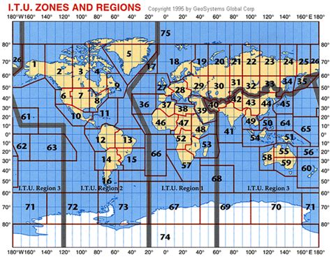
Look at the top line of v2.8 PowerSDR. It will contain the Model#, Serial#, and Turf "Region" of your Flex Radio.
Current list of "Regions":
US = USA, CA, ROW
UK
Europe = Germany, European Union, IARU1
UK_Plus = UK+ (adds 60m band)
Italy
Norway = Norway, Czech Rep.
Denmark
Latvia
Slovakia = Slovakia, Malta
Bulgaria
Greece
Hungary
Belgium
France
Russia
Sweden
IARU3 = China, Australia, New Zealand
Japan
Italy_Plus = Italy+ (40m band)
ES_CH_FIN = Spain, Switzerland, Finland
Netherlands
EU_Travel
Luxembourg
IARU2 = Central & South America
Australia
China
_______________________________________
The TURF region determines your Band Privileges (where you can transmit)
The TURF region is programmed into the Radio's EEPROM
Once you update the TURF Region of your Flex Radio, cycle power,
Run PowerSDR
setup->General->Options. Click on "Update BandText" button
This will update the "Band Text" that appears just below VFO-A and VFO-B
to match your "Region"
NOTE: If you just added 60m band transmit to your Flex and you run into trouble, search this webpage for:
60m update to IARU Region 1
NOTE: Firmware updates provided in PowerSDR software will NOT disable your "Extended" or MARS operation.
So dont worry.
_______________________________________
MARS / SHARES operation (Extended operation)
The Flex-1500, Flex-3000, Flex-5000 can be made to operate in "Extended" or MARS/SHARES mode.
SHARES=SHared RESources High Frequency Radio Program
(see https://www.cisa.gov/shared-resources-shares-high-frequency-hf-radio-program for details)
MARS=Military Auxiliary Radio System (and AFMARS Air Force MARS)
(see https://www.mars.af.mil/ for details)
NOTE: Firmware updates provided in PowerSDR software will NOT disable your "Extended" or MARS operation.
So dont worry.
If your Flex Radio has MARS (Extended) operation enabled, the top line of v2.8 PowerSDR will not only show your TURF Region but also show the word "Extended"
The Flex-5000a links to a Windows PC via a 400Mb/s IEEE1394 FireWire cable
PowerSDR Ver 2.7.2 SVN 5123 (Rev L) (in Program Files(x86) folder)
FlexRadio Ver 4.1.3 (in Program Files folder)
Flex-5000 Firmware Ver 2.1.3.9 (under Program Data folder)
Flex 5000 Specs (based on what I can determine):
ARM7TDMI 32bit processor, AD9511 master clock (500 mhz), AD9959 10bit 500msps DDS for generating the LO (seperate outputs for RX and TX), AK53394A 192khz A/D for RX (IF), CS42448 for A/D & D/A audio in/out, 74CBT3253PW used as a digital mixer (1 for TX and 1 for RX).
TX output signal is created by mixing the D/A CS42448 audio thru a 74CBT3253PW mixer with the AD9959 LO
RX input is determined by mixing the AD9959 LO thru a second 74CBT3253PW mixer with the Antenna circuit, then sending the I/Q signals to the AK5394A for 192khz bandwidth
Where the Flex 6000 series and Hermes SDR's use an A/D capable of directly sampling RF energy (so you can view huge sections of RF at one time), the Flex 5000 uses a LO to mix down the RF directly down to a192khz window.
Newer SDR's (like the Flex-6000 series) perform DSP Internally, where prior generation SDR radios required a PC for the DSP.
While the 5000 is no longer state-of-the-art, it still remains a top receiver (see https://www.sherweng.com/table.html)
Locations of fellow PowerSDR users around the world, and those currently viewing this page:
|