![]()
![]()
![]()
![]()
![]()
![]()
![]()
![]()
![]()
![]()
![]()
![]()
![]()
![]()
![]()
![]()
![]()
![]()
![]()
![]()
Select your Language:
How does a Radio Antenna function?:
A "charge" (i.e. excess electrons) produces an ELECTRIC FIELD. A moving charge produces both an Electric field and Magnetic field.
When you oscillate a moving charge (which is what happens when you transmit into an antenna), you get oscillating electromagetic fields
Oscillating fields propagate out into the ether every time the field Oscillates (ie. charges reverse direction at the end of the oscillation).
These Osc fields have a strength and wavelength. These Osc Fields can be in the Radio freq range or visible light range, its all the same.
The smallest piece of these electromagnetic fields (quantum) is the "Photon" (whether light or RF, its still a photon.)
When an Osc electromagetic field encounters external matter (air, glass, water, trees, metal), the available electrons in that matter will now begin to oscillate. This in turn causes the electrons in this matter to generate their own electromagetic field for as long as these electrons remain in the presence of the external osc electromagetic field.
The type of matter being struck by this oscillating field (along with the 1st fields strength and wave length) will determine the wavelength and strength of this new 2nd oscillating field that comes into existance.
For example: Glass will not generate much of a 2nd oscillating field when exposed to RF fields, but a metal pole will.
The two oscillating fields combine (Superposition), which can result in either strengthing/weaking of the resulting osc field in certain directions.
This means that the shape & distance between the Antenna and external matter being struck are very important to the resulting osc field.
Because our radio antennas are surrounded by matter of all kinds (which means the electromagnetic fields will be altered by the surrounding matter), the resulting performance for any antenna depends on its location (i.e. distance to the ground, ground conductivity, other metal structures, etc.). The Frequency of the Osc fields also determine
The direction of the photons (Electric Field) come off at right angles to the direction of the wire. So in a dipole the oscillation goes from tip to tip, so the photons jump off and propagate perpendicular to the wires (360deg around the wire but perpendicular) with the peaks & troughs running parallel to the wires. BUT the photon propagation are quickly shaped and directed by "superposition".
There are 2 types of superposition. 1) Phasing of Emitters so photon electric fields add or subtract directly. 2) Photons from your antenna interact and cause electrons (in atoms) around your antenna (i.e. ground, directors, reflectors) to move (feel force from the electric field of the photons) and hence generate their own electric fields. All these electric fields are added or subtracted using "superposition". (i.e. adding a director 1/4wave from the dipole causes photon electric fields to cancel behind the director but add (reinforce) in front of the antenna).
So, Photon interaction with objects
around your antenna (especially Earth itself) create big changes to the propagation pattern of your antenna.
This is similar to the way "Light" bends and slows down as it enters water (photons of light cause electrons in the atoms of water to generate their own electric fields.) This is all because superposition between the electric fields not only changes the strength of the sum total electric field (which manifests as a change in directional force), but the speed of the wave propagation and hence the overall speed of the photons.
But since we cannot see the actual photon emission of RF off an antenna (with our eyes), we must rely solely upon formulas and testing our antennas directly in their end use environment.
Then to have those transmitted photons strike a receiving antenna and be absorbed (in a reverse process), causing AC current to flow in the antenna wire of that "Receiver". The more wattage flowing in your antenna, the more photons jump off. The higher the frequency, the more energy each photon has. Each photon travels until it is abosorbed. Depending on its energy level, it may pass through certain materials or be absorbed by certain materials (especially conductive materials with RF generated photons). As you move up the frequency spectrum, the energy level of photons, combined with the quantity of photons, can be used to heat objects.
A "transformer" (Magnetic Field is similiar to the Electric Field, but from a different frame of reference) works similarly to a radio transmitter/receiver antenna setup, photons leave the primary coil (due to an AC current flow), but get mostly absorbed by the secondary coil. So the photon emission is all internal to the transformer.
Receiving antenna's must be designed to efficiently convert photons (generated by the sender at radio frequencies) back into AC current in a wire. Since we are dealing with AC currents, the antenna must be tuned so energy created by the photons doesnt get lost, but gets back to the "Receiver" at the end of the antenna.
Transmitting antennas must be designed to emit the most photons in the desired direction. This may be parallel to the ground or at a slight elevated angle to take advantage of "Skip". The idea is to get the transmitting antenna to have the largest AC current flow possible to get the largest number of photons, but also to get them going in the intended direction. And, not have the photons you just emitted be absorbed by anything nearby.
1) G5RV dipole (102' long): homemade All-Band(80,40,20,17,15,12,10,6m) 35' off the ground, with a 1' diameter 10 turn coax choke at the bottom of the ladder line (at ground level). Performance is very good on 80m/40m (much quieter than the verticals), but sub-par on 15/12/10m. Surprised that it works on 6m without a tuner.
Theory of a G5RV:
The standard G5RV is a 102' long 1/2wave center-fed dipole on 20m (with the 34' of ladder line acting as an impedance match). While the ladder line does not radiate it does effect the length of the antenna, so you cannot change its length (but you can change the coax length). I add a coaxial choke to keep any RF off of the shield of my coax going back to the shack. A tuner is needed on all other bands (except 20m). High voltage appears at the tips of the antenna and at the bottom of the ladder line. On 80m & 40M it effectively acts like a 1/2wave ant with a tuner to virtually adjust out length. On 20m it is a 1/2wave, On 17-10m it starts to act as a long wire antenna and performance suffers. Im not sure what is happening on 6m. See below for 160m
Left: interface of Ladder line to Coax RF choke. Right: G5RV in the trees


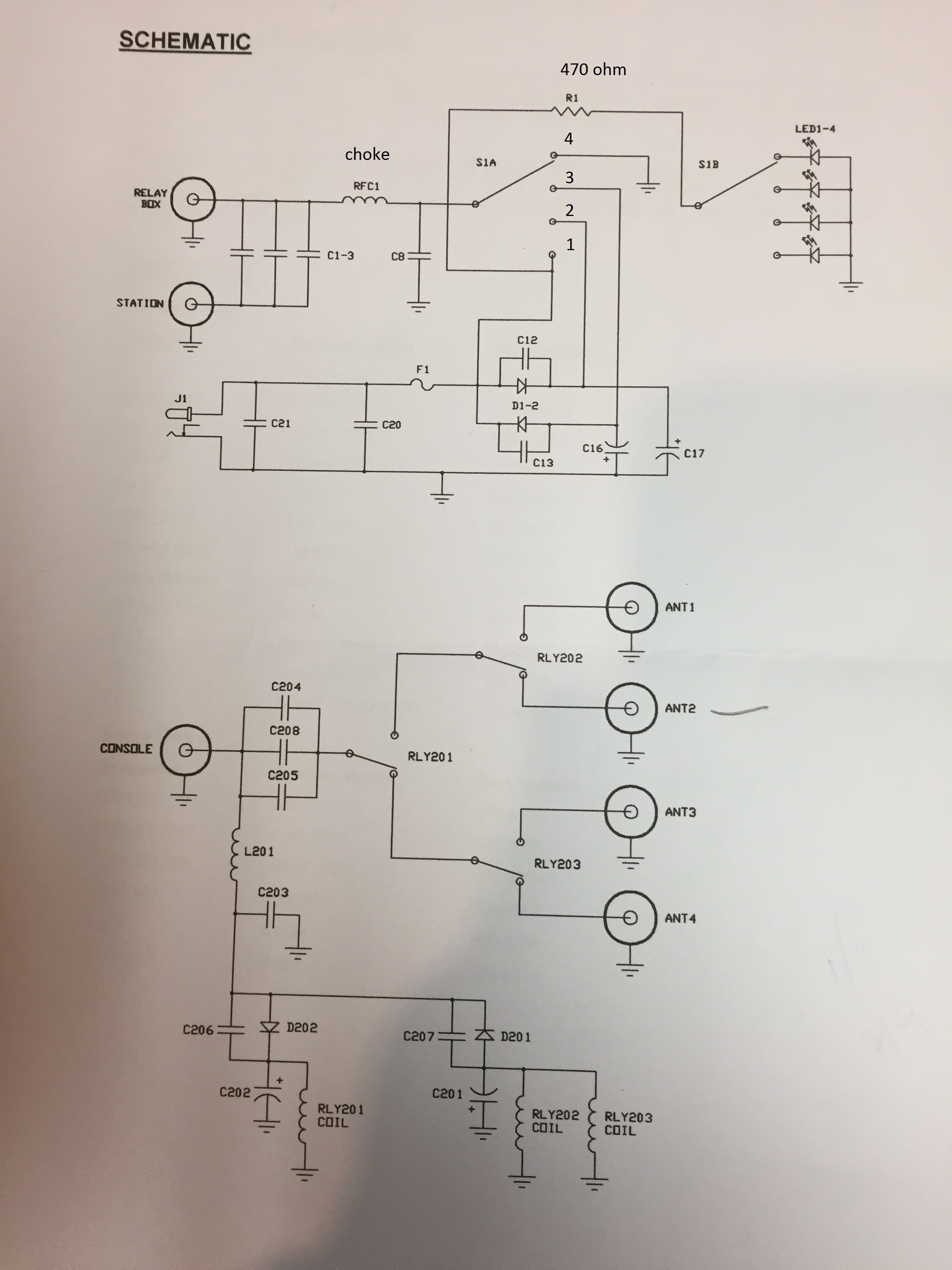
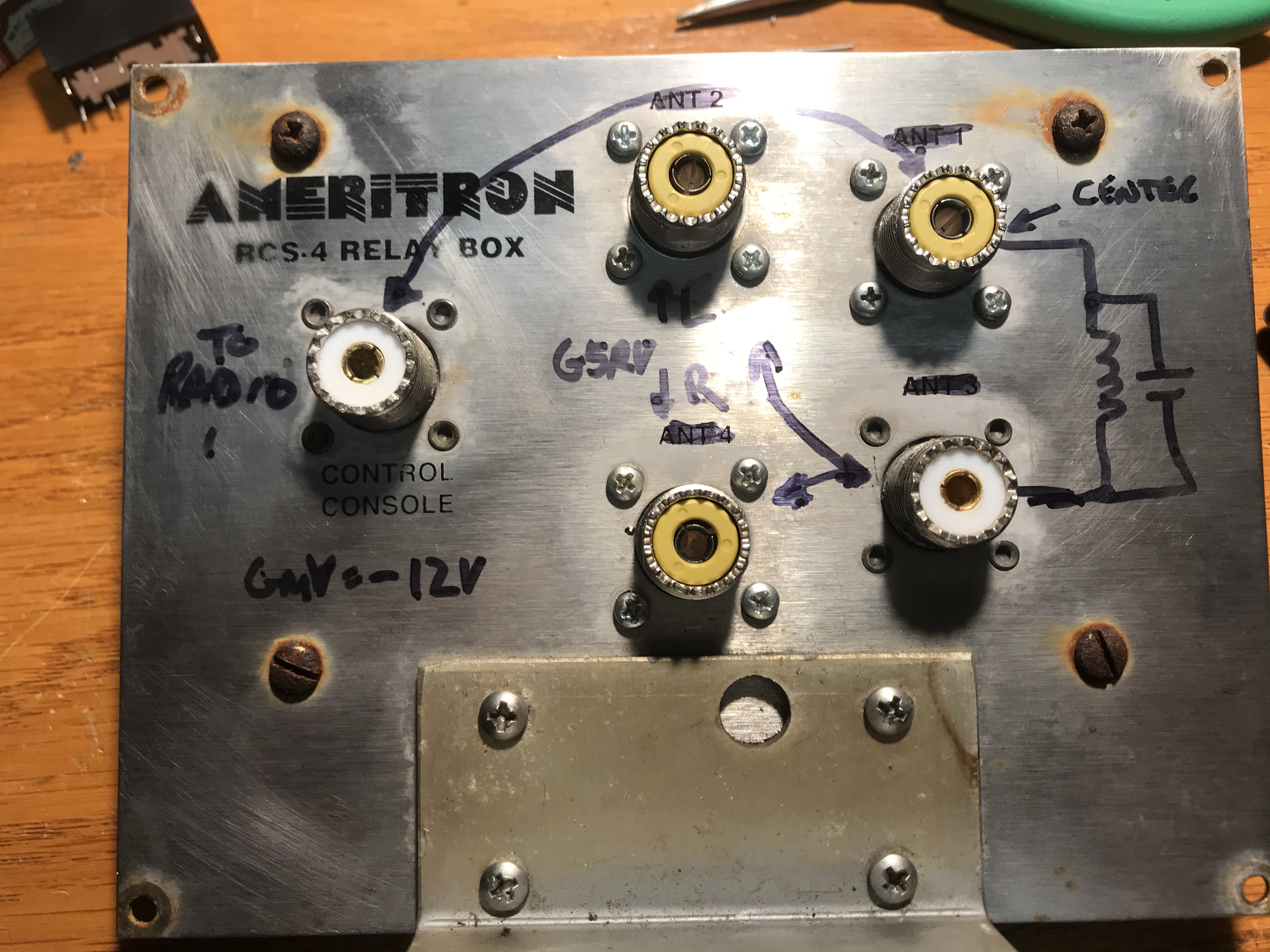
Left: G5RV (160m modification) control box.
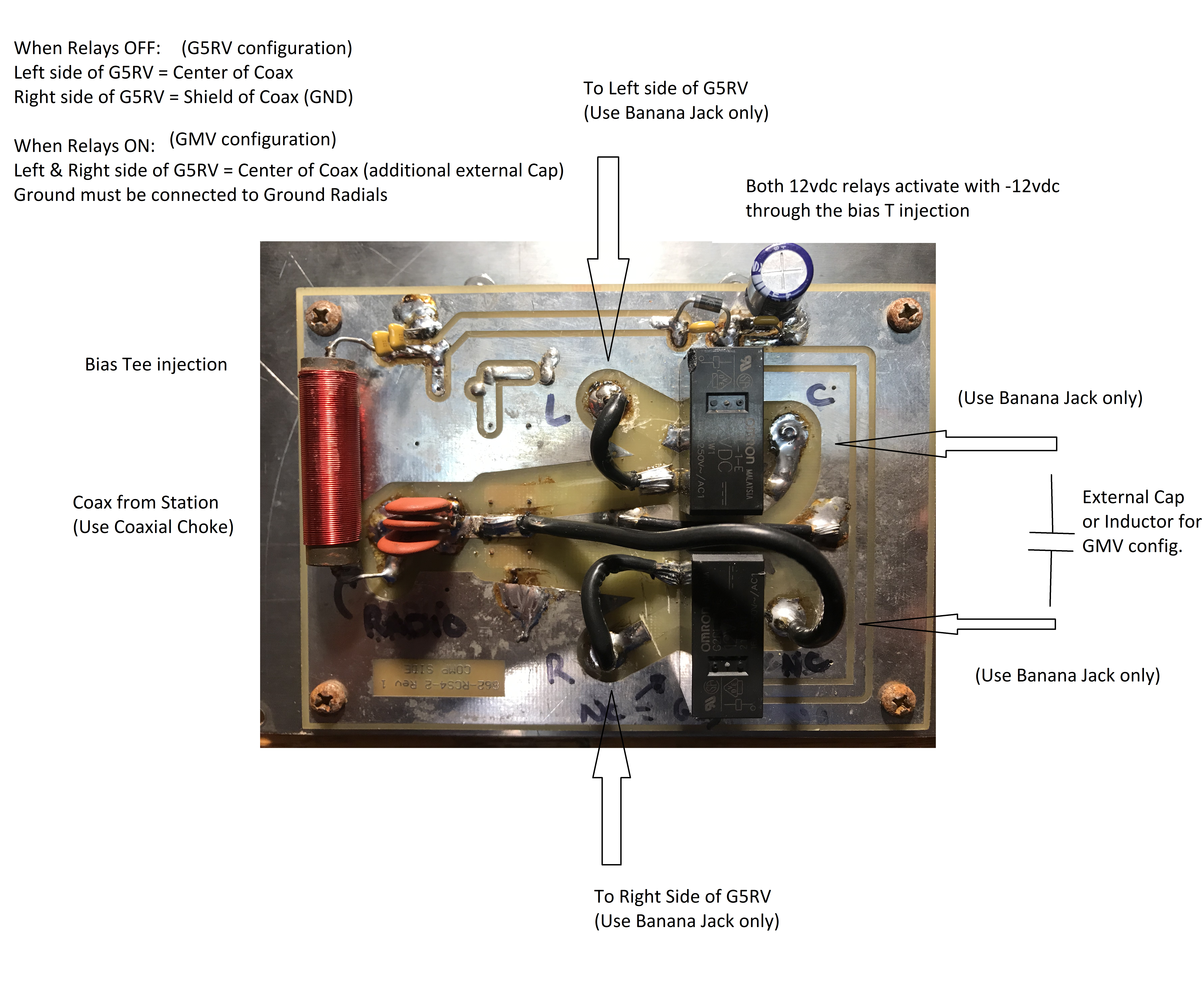
Right: Inside view of a modified RCS-4 control box to switch IN/OUT ground radials for 160m

Left: G5RV PCB Ladder line to Coax interface. Right:
Click on any picture to Enlarge
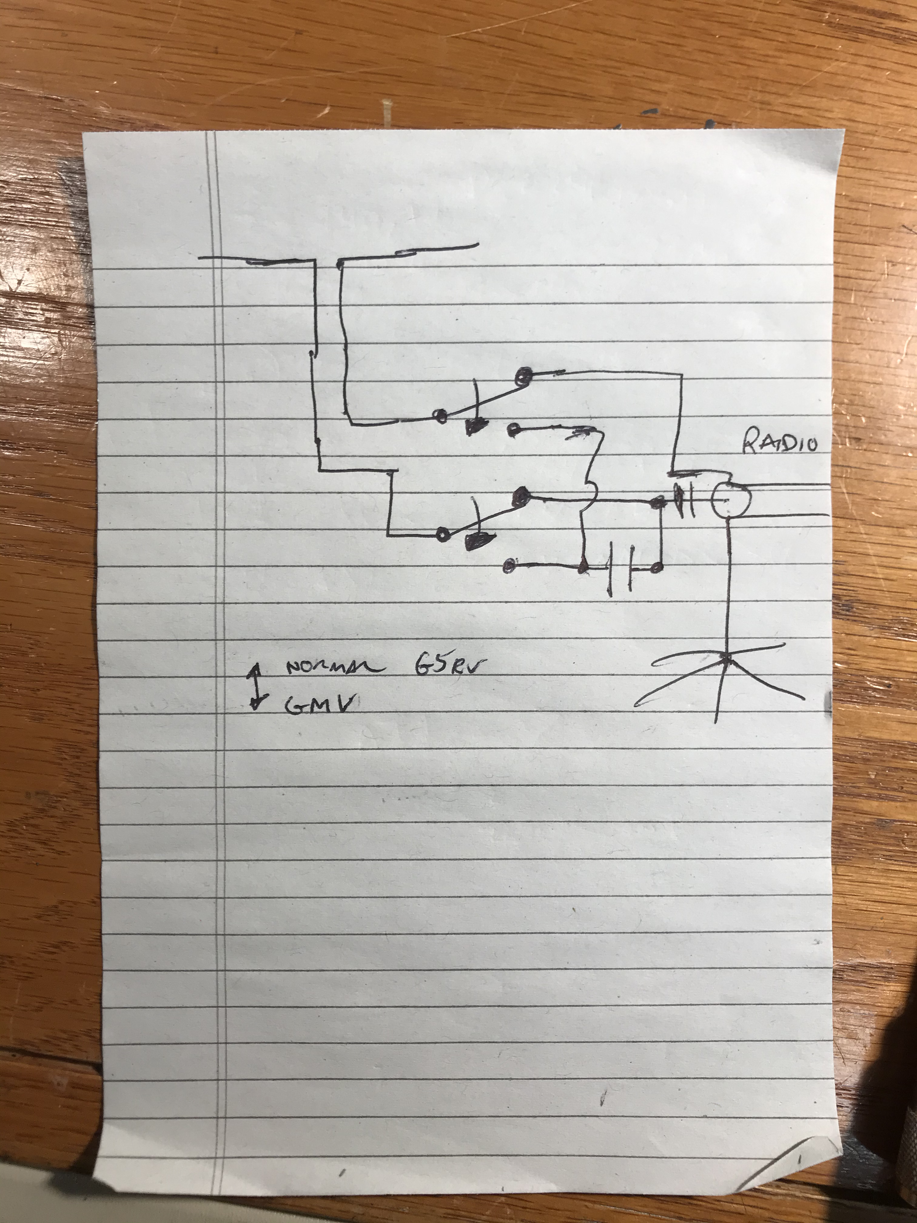
160m G5RV modification: Using (25) 44' radials (from my previous Ground mounted Vertical) layed directly under the ladder line of the G5RV, I can electronically reconfigure the standard G5RV into a 160m antenna.
The idea is to short both sides of the G5RV to the center of the Coax, and connect the coax shield to the Ground Radial system directly under it.
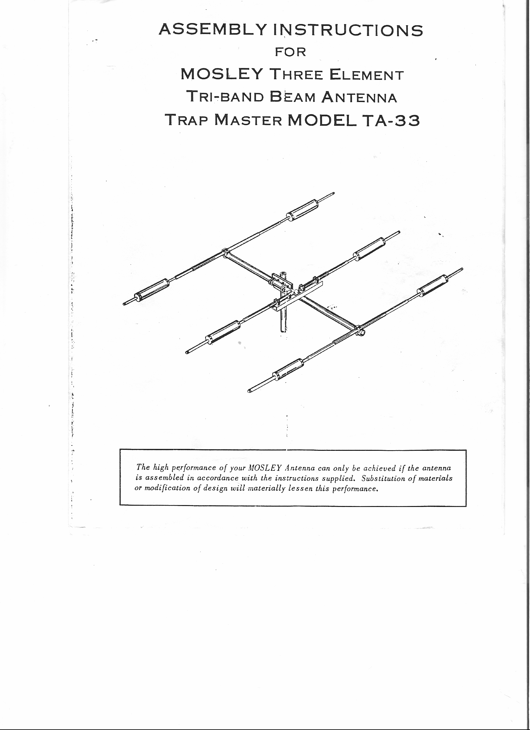
2) Mosley TA-33 Junior 3 element Tri-Band (20,15,10,6m). On top of the house. with Hy-Gain CD-45-II rotator system.
Performance is excellent on 20/15/10m. Again, surprised it works on 6m without a tuner.
.JPG)
Picture showing the Mosley
--------------------------------------------------------------------------------------------