DDS Design
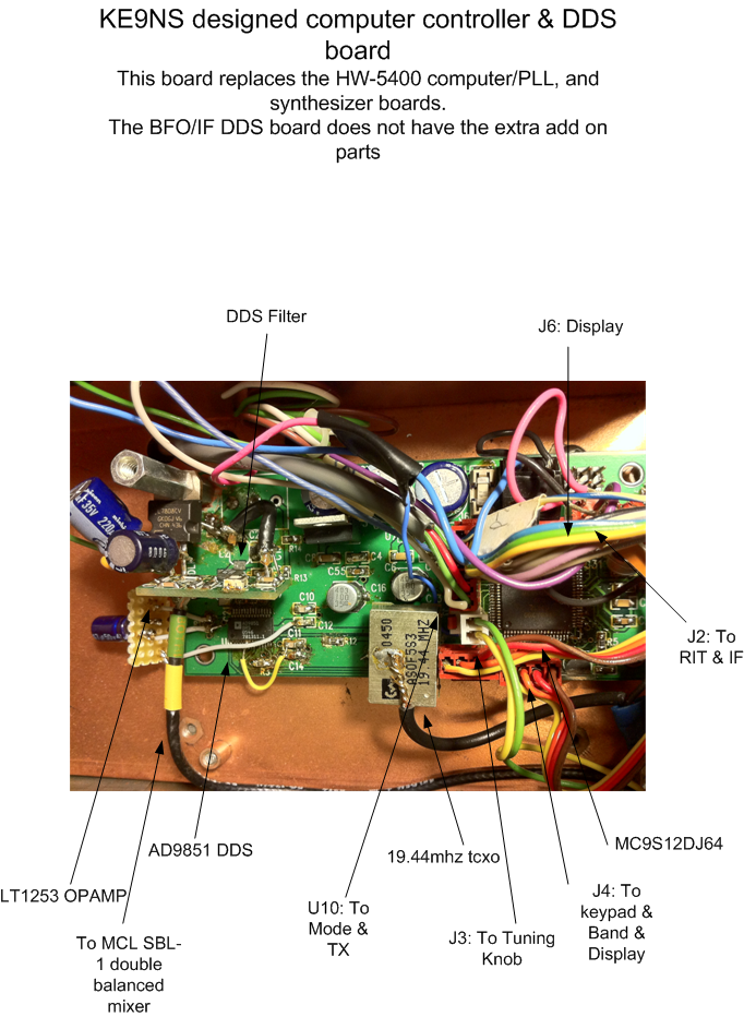
The DDS project is based upon a single chip Analog Devices AD9851 Direct Digital Synthesizer capable of resolutions under 1hz using a 32bit tuning word, and a range that runs through and past the HF spectrum (up to 60mhz), and a capability of changing frequency at a rate of 23million/second. Only a low pass filter is required
The DDS chip does require an external CPU to feed it the frequency as a 40bit tuning word. I chose the Freescale MC9S12D64 for its all-around performance and features: low speed external clock but runs intenally at 50mhz, flash memory, 10bit 8 channel A/D, and plenty of I/O. The CPU controls the DDS via 1 high speed serial pin line.
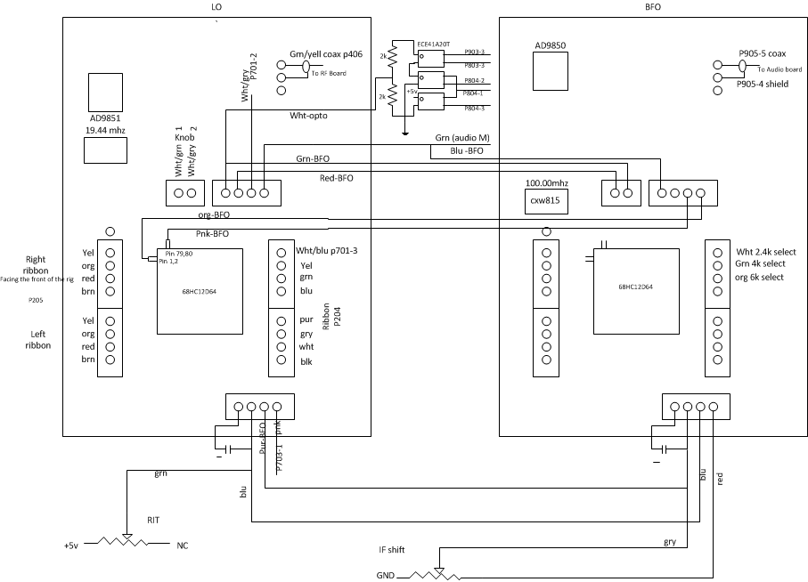
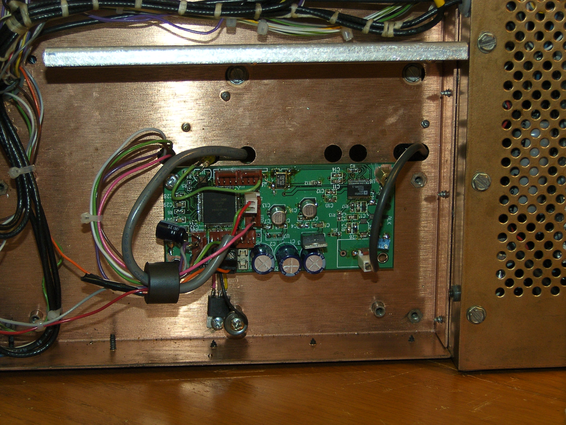
DDS LO board
The "LO DDS" 16bit CPU controls all of the radio functions,
including the VF display, keypad, tuning knob, memory buttons, band
selection, mode selection, and LO frequency generation. The tuning knob is fully optical and sends digital
signals to the interrupt driven CPU for frequency changes. The keypad allows for direct frequency control as well
as turning on/off special functions. The EEPROM stores 5 frequencies for each band
(selectable from the keypad)
Manual "RIT" adjustments are made via the front panel knob. The original "RIT" control (10k pot) is rewired to the CPU's A/D converter. The A/D information is converted into frequency shift information for RX only. The "LO DDS" board maintains the proper RF frequency by adding the exact same "IF DDS" frequency to its own LO frequency. This is achieved by making sure the "LO DDS" and the "IF DDS" boards see the same information.
The radios SBL-1 mixers require +7dBm LO, in
order to operate properly. Output level (dBm) of the "LO DDS" is too low
on the 10m band (LO = ~36 mhz), requiring an additional OP-AMP to boost
this level.
Single Side Band Modulation
SSB generation is accomplished via the DDS IF board.
(
This replaces the original BFO board.)
An idiots guide to SSB generation, via the FILTER method:
1) Apply audio and an IF sine wave into a balanced modulator. We not only want to mix the audio and IF to produce an audio modulated IF signal, but eliminate the carrier (the RF envelope generated when the transmitter is active, even when there is no audio present) by balancing out the audio modulated IF signal sent to the LO mixer. The idea is to have no output signal if your not talking.
2) Now you have a DSB (double sideband) signal in which the audio modulated IF signal only appears at the input of the LO mixer when you apply audio (i.e. talk into the mic). If you keep your IF freq at the center of the IF filter, any AM radio can properly detect your audio signal, since AM is DSB with a carrier all the time.
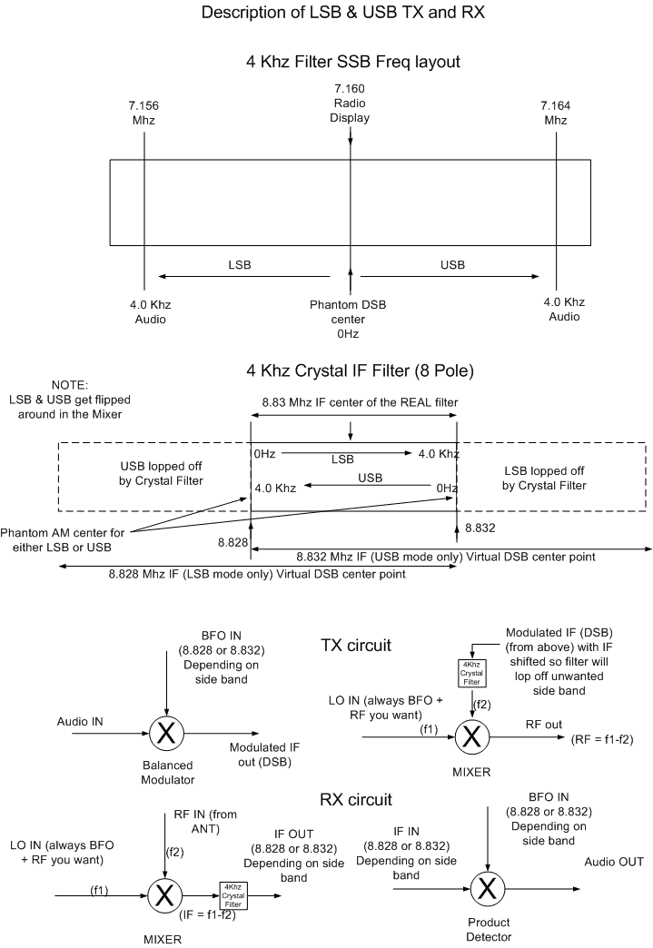
3) In AM, the carrier is in the center of the IF crystal filter and allows audio signals both above and below the IF center freq. In SSB there is no carrier, so a phantom carrier IF freq is located on either the low edge or upper edge of the selected IF filter. The idea is to use the crystal filter to allow audio signals either above or below the phantom carrier freq, but not both.
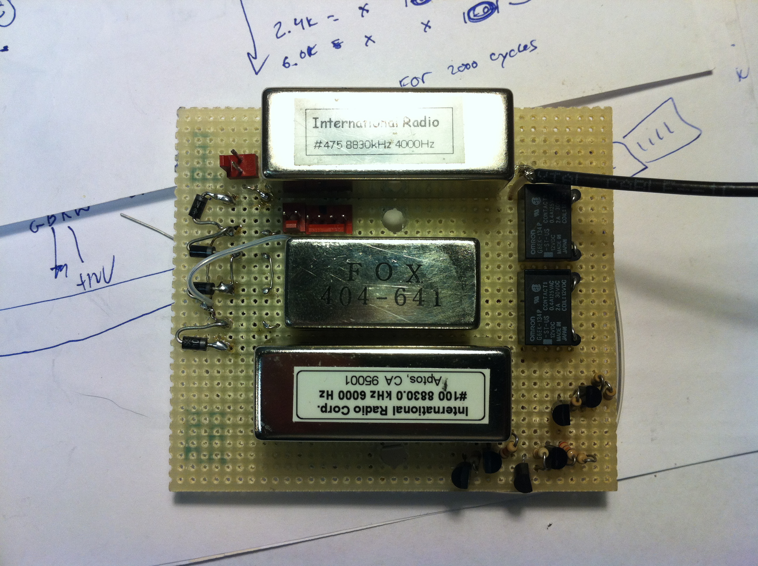
This example is for a 4Khz wide 8.830MHz crystal filter
Lower edge Filter center Upper edge
IF 8.828 ________ AM IF 8.830 ____ ___ IF 8.832
|| -2khz AM Passband center 2khz ||
|| 4khz USB signal between the lines 0hz || <-phantom carrier point
Phantom carrier -> || 0hz LSB signal between the lines 4khz ||
4) This method requires that the LO freq be adjusted to the IF freq your using. That is the RF freq. of interest is obtained by selecting a LO freq = IF (carrier or phantom carrier freq) + the RF freq.
5) Shifting the IF freq, shifts the phantom carrier freq, which in turn moves the audio passband.
With a USB signal, moving the IF up in freq. will raise the freq. response audio received because your moving your virtual 0 HZ audio point (phantom carrier point) away from the actual received audio signal. Moving the RF up in freq will lower the freq. response audio received because your moving the received signal back towards the 0Hz audio point (phantom carrier point), or maybe even past.
Here's a better description of what goes on inside the HW-5400 radio to generate SSB using a 4k crystal filter:
Click to enlarge picture
Stability of the LO DDS comes from using a rather expensive $100 reference OCXO (Oven controlled crystal oscillator) at 19.44mhz (+/- 0.25ppm). The DDS multiplies this by 6 for a 116mhz +/- 29hz (worst case). The DDS max output is (10meters) 30mhz+IF=38.830mhz, so output/input ratio is 38.83/116 = .335. The DDS output will vary worst case of +/- 10hz. The IF DDS output is 8.83mhz and so only requires a standard inexpensive $5 100mhz +/- 25ppm crystal since the output/input ratio is so low. The other way to achive stability would be to use a DDS with a built in PLL circuit and a low freq crystal reference.
Base IF 8.830 mhz: The 2.8kHz filter was moved off the IF board and placed on a new circuit board that allows mechanically switching in/out either the original 2.8kHz filter or a new 4kHz filter. This requires the IF freq. to be shifted to different phantom carrier frequencies (depending on the MODE and FILTER width) for SSB operation. Using the 2.8 kHz IF crystal filter: "IF DDS" at 8.828550 LSB & 8.831450 USB (+/- 1450 hz from center) Using the 4.0 kHz IF crystal filter: "IF DDS" at 8.828000 LSB & 8.832000 USB (+/- 2000 hz from center)
The "LO DDS" also shifts its LO freq according to the MODE and Filter width to keep your RF freq. constant. Digital signals sent from the "LO DDS" board indicate the operating mode (AM,CW,LSB,USB) to the "IF DDS" The "IF DDS" board produces the correct IF frequency based on this information.
Manual "IF shift" adjustments are made via the front panel knob. The "IF shift" POT is wired to the CPU's onboard A/D converter. The A/D information is converted into frequency shift information. The "IF shift" POT is also sent to the "LO DDS" board to keep the RF freq. constant.
The DDS IF output level is adjusted down to ~200mv p-p (via a POT) for use by the balanced modulator in both RX and TX circuits of the AUDIO board.