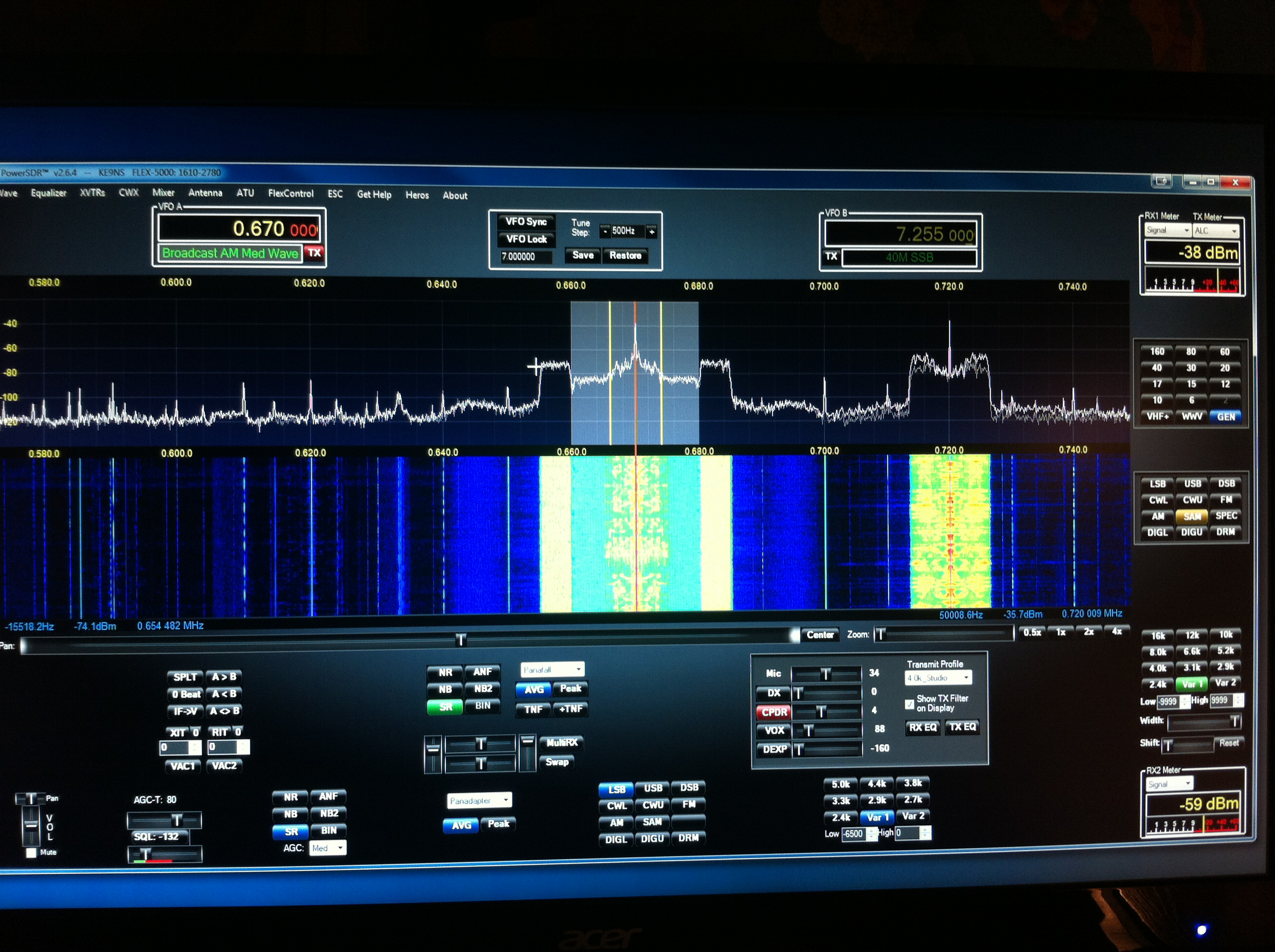
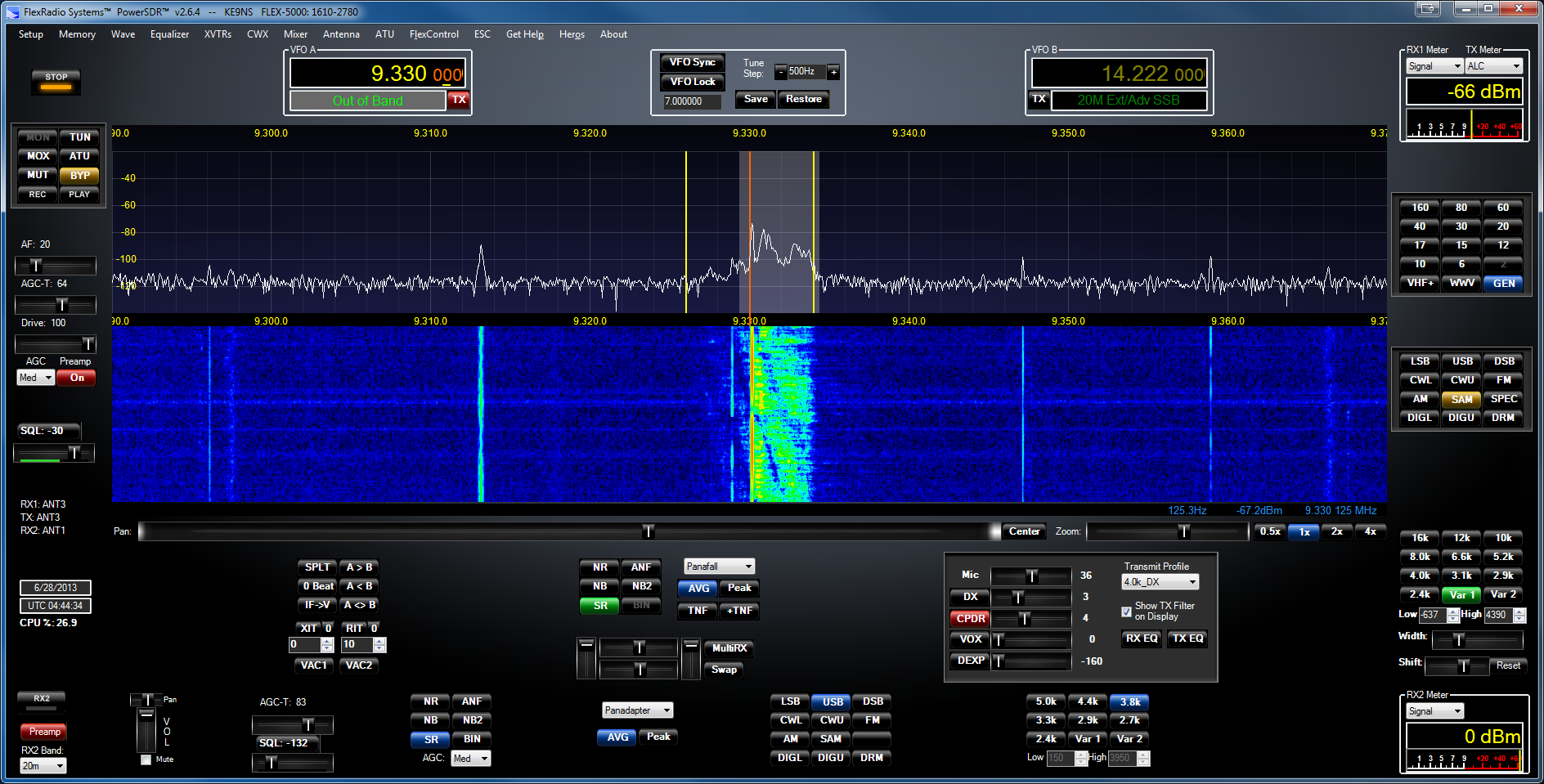
Windows PC DPC Latency and High CPU usage
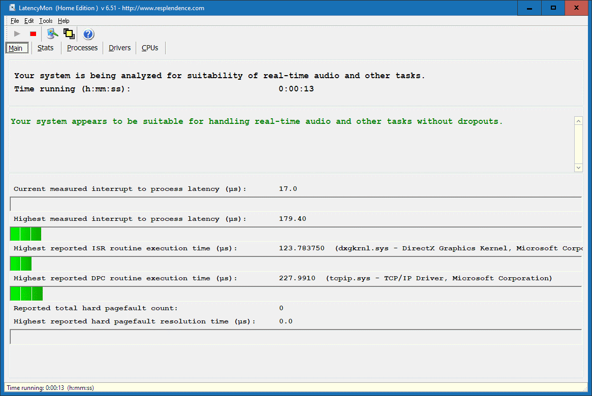
If you find PowerSDR is freezing up, you may have a DPC Latency issue:
DPC latency has to do with real-time background processes.
When you open windows Task manager you will see all the programs and processes that run in the background.
So even if you have a high number of cores, it can still happen, do to a faulty driver, or a bad program, or virus.
Also, hard drive activity can cause latency as well (I switched to a Solid-State 1Gb drive a couple of years ago.).
There is only so much background time available in order to keep a process running in real-time.
Programs that can help find out what your PC is doing:
Windows Task Manager (right click in the windows tray to select): Show all the Apps and Background Processes running with the CPU,Memory, HDD, network loading.
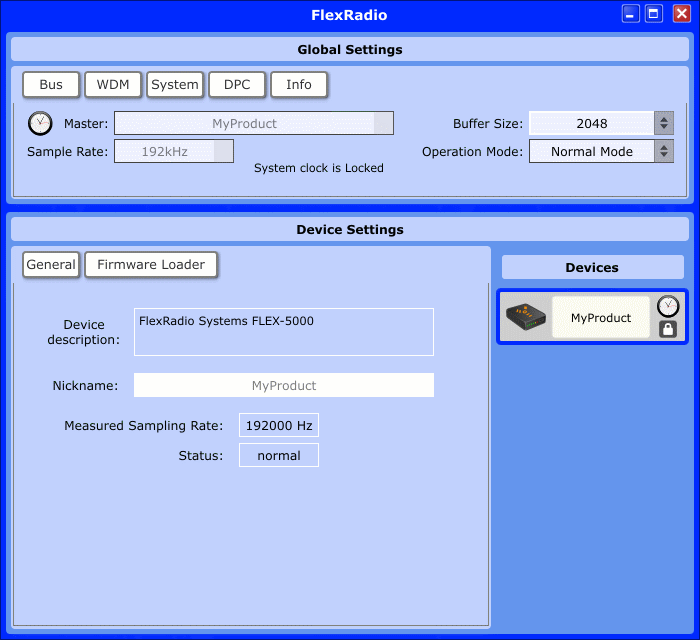
FlexRadio.exe (windows control panel): View DPC latency in time.
WhySoSlow.exe: You can generate a report showing what might be causing it.
Latency Monitor (LatMon.exe): Test for DPC latency
Process Explorer (procexp.exe) will show you all code running (this can be scary when you see it) and how much CPU time.
Autoruns.exe or CCleaner.exe: You can see what exactly gets loaded at Startup
___________________________________________________________________
CPU % not functioning or Temp & Volts not working:
Click Start, type "cmd" in the Search box.
Right click cmd.exe, and select Run as administrator.
At the prompt, type lodctr /R and press ENTER. (note the "R" is a capital letter)
This will repair the PerfMon pointers (those are stored in the registry).
You should see this message if the process was successful:
Info: Successfully rebuilt performance counter setting from system backup
If this results in an ERROR, then try the following:
Type: C:\Windows\SysWOW64>lodctr /R
You should see: Info: Successfully rebuilt performance counter setting from system backup store
Then type: C:\Windows\SysWOW64>winmgmt.exe /RESYNCPERF
This will hopefully fix a Windows PerfMon issue.
____________________________________________________________________
NOTE: FT8 & JTAlert-x have a rather large penalty on your CPU in a crowded band (like 80m and 40m) trying to decode 20 or so signals simultaneously. The more signals to decode, the higher CPU. My old 4 core cpu maxed out at 100% decoding on 40m and running PowerSDR at the same time.
I decided to upgrade my desktop motherboard to an AMD Ryzen 6 core (12 thread) and 16gb of DDR4 is more than enough horsepower to run everything and anything, and allows PowerSDR to run at 30fps and the analog meter movement to run at 40msec with 3 - 6% cpu.
link to Upgrade to the latest version of Win10 (should be free if you have the key from a prior version of Windows):
https://www.microsoft.com/en-us/software-download/windows10
"Change Active Hours" (Win10)
In Windows 10, go to "Windows Update" and change your "Active Hours" to reflect your time on the radio to prevent a windows update during the time your using PowerSDR.
Privacy Settings (Win10)
UnderWindows 10 you will want to turn all the new privacy settings and "how updates are delivered" to OFF (block) . Otherwise your computer will be allowed to constantly send data not only back to Microsoft & others, but allows others to use your computer as an "Update server".
Microsoft "Store" (Win10)
Open Windows STORE app. In the upper right corner ... click and select setup. Turn off automatic updates of Apps,otherwise Windows 10 will be constantly downloading and installing apps while PowerSDR is running.
Microsoft monitoring (Win10)
Turn OFF "Microsoft Compatibility Telemetry"
(huge drive and cpu usage hog that can start running in the background at any time while running PowerSDR) (text procedure to disable it here)
Turn OFF the following Windows "Task Scheduler" items:
---- Microsoft Compatibility Telemetry
(huge drive and cpu usage hog)
---- Customer Experience Improvement
----
Power Efficiency Diagnostics
---- Windows Defender (start hard drive scans manually yourself when you want )
---- Media Center
(Since it Windows 10 no longer allows the program to run)
Turn OFF the following Windows "Services":
All the "Diagnostics ..." services including: policy, service, system, Tracking (assuming all your components are working)
Lfsvc: Geolocation
service windows 10
Fax: fax
Homegrouplistener: Homegroup HomeGroup continuously scans your network for files, printer, devices, data
Homegroupprovider: Homegroup
Media Center:
continuously scans your network.
WMPNetworkSvc: Windows Media sharing
Windows Search (indexing) continuously updates its index files every single time a file is created, which keeps the CPU(s) & Memory & HDD busy.
Turn OFF
network Printer SERVICE: HP and others have poorly written network printer Services that will continuously eat up CPU & Network.
Turn OFF MSCONFIG STARTUP programs that check themselves for updates (i.e. java, adobe, apple. do the update checks yourself). You can use free CCLEANER.exe to find them and disable them.
Schedule your Virus Checker program to update itself & scan at off hours. Dont run the virus scanner when you are using the PC.
Many Virus scanner program do background optimization without your knowledge. Usually the only way to quiet them down is to put them into Gamer Mode or Silent Mode.
Disable Windows automatic updates. Do the checks yourself.
Leave your computer ON, set for HDD & monitor to turn off after 20min of no use. This way the OS doesnt spend time after start-up to do housekeeping.
Some Video card drivers(i.e. Nvidia) include Gamer previews that download and update without your knowledge. You will want to
make sure you check the "Task Manager" to see any programs that are running and delete them. If you have an NVidia card you will want to check this link to turn off the Nvidia PowerMiser feature: here
Run "Task Manager" (right click on the task bar and select "Start Task Manager" then click on the "Show processes from all users". This will show all the hidden processes that require ADMIN privileges to stop. Check them to see if any sneaky programs are running.
IF YOUR VIDEO CARD IS POOR: Go to System Properties-> Advanced ->Performance Settings-> Visual Effects->Adjust for best performance (to turn off the graphics extras that you probably dont need)
To speed up your computer, get a new Solid-State Hard drive, and a Gamers video card.
To Enable/Disable Windows Services: Click on the Start button and type "services" in the search window.
Click on Services (local).
FINALLY:
Right CLICK on the task bar (bottom of the screen) and select "Start Task Manager", then click on the "show processes for all users" down at the bottom.
Its good to print this screen out for future reference when your computer starts to "act"
up.
Kill rogue programs that are running in the background (like java update scheduler, ituneshelper,etc.).
Also, check the "Task Scheduler" to make sure Windows or other programs dont run a schedule task while your operating.
Programs to Download and Install besides PowerSDR
(These programs are explained further down below)
For multiple virtual CAT/COM port pairs:
1) VspMgr (x64 free): Allows you to create multiple "Virtual COM" port pairs to be used with DDUtil to allow CAT control of multiple PC programs at the same time. https://k5fr.com/DDUtilV3wiki/index.php?title=VSP_Manager
(NOTE: run only in ADMIN and XP SP3 compatibility mode)
Think of a virtual CAT/COM port pair as both ends of a single RS232 Cable (each end of the cable needs to have its own COM port#)
Or if you dont like VspMgr try:
com0com_x86_signed
OR
com0com_x64_signed
For VAC (DAX):
2) VoicMeeter Banana (free): Creates a "Virtual Audio" Channel (in & out) which allows your Flex to send/receive audio from the PC. This allows you to use MME, Direct Sound, and WDM-KS drivers. This is the best I have found. https://vb-audio.com/Voicemeeter/banana.htm
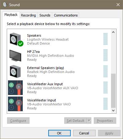
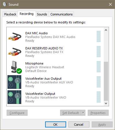
These cables will appear under the SOUND panel as "VoiceMeeter IN/OUT" and "VoiceMeeter Aux IN/OUT". Each of these is a 1 direction audio cable.
Think of a virtual audio channel as a single RCA cable, one end is the Input, the other end is the output. And the AUX cable is a second RCA cable.
For a 2nd set of "Virtual Audio" cables go and download: https://vb-audio.com/Cable/index.htm
These cables will appear under the SOUND panel as "CABLE IN/OUT". This CABLE is bi-directional and so there is no AUX IN/OUT cable needed.
-----------------------------------------------------------------------------------------------------
4) WSJT-x (free): FT8 digital mode and more. https://wsjt.sourceforge.io/wsjtx.html
5) JTAlert-x (free): keeps track of needed contacts and prevents dups (has a callsign database download as well). https://hamapps.com/
6) CWSkimmer: Use to Decode multiple CW conversations. Use the built in CWX to transmit CW if you dont have your own key.
7) HRD
5.24.0.38 (free): Ham Radio Deluxe last free version gives you a Log book and digital modes that link to the flex via a CAT COM port.
8) Fldigi (free): Multiple Digital modes (now located on sourceforge as a setup file) http://www.w1hkj.com/index.html
Here is the PowerSDR.xml file, unzip and drop in the folder with fldigi. Just right click on the fldigi icon and open file location
For specialized AMP, Rotor, etc control of those CAT/COM ports (no longer a need to use it for multiplexing COM ports:
9) DDUtil_V3 (free): Scans the CAT port you assigned in PowerSDR (setup -> CAT Control) and allows you to map the PowerSDR COM port to multiple COM ports created by "VspMgr" or "VSPE". This will allow you to have multiple PC programs all talking to your Flex at the same time. https://k5fr.com/DDUtilV3wiki/index.php?title=Download
10) EasyPal (free): Allows you to exchange quick Internet pictures by sending links to them over the radio. Also allows for Waterfall callsign ID images. https://www.vk3evl.com/index.php?option=com_content&view=article&id=57&Itemid=62
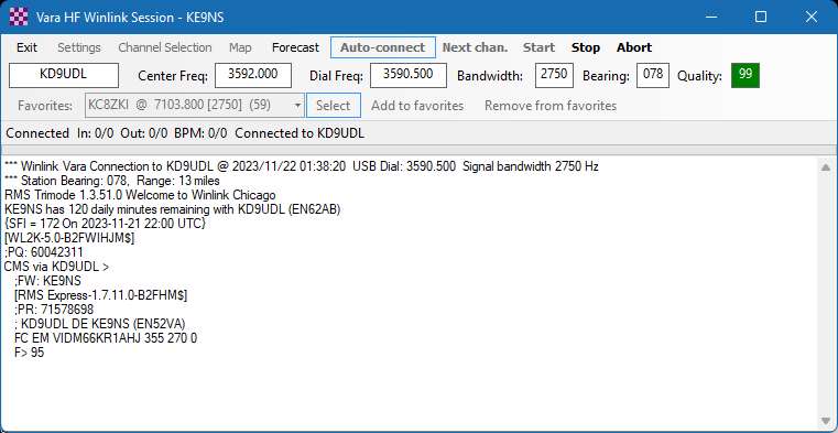
11) Vara HF and FM weak signal modems (used by Winlink Express):
https://rosmodem.wordpress.com/
Audio Folders (location of REC / PLAY), MP3 & PowerSDR Database
The QuickAudio file names now contain a sequential index value + Mode + freq + date + time of the recording
Every time you hit the REC button a file "SDRQuickAudioXXX.wav" is created in the folder:
%userprofile%\AppData\Roaming\FlexRadio Systems\PowerSDR v2.8.0\QuickAudio\
(Right Click on the PLAY button to open this folder)
and (Wave->MP3 folder) an "SDRQuickAudioXXX.MP3" is created in the folder:
%userprofile%\AppData\Roaming\FlexRadio Systems\PowerSDR v2.8.0\QuickAudioMP3\
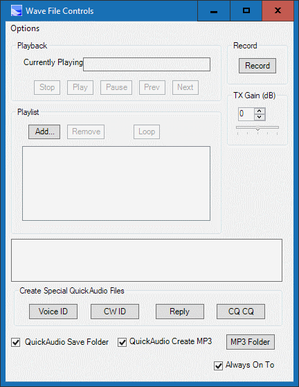
Click on the "Wave"
button then "MP3 Folder" button to open the MP3 folder directly.
The file location of the "MEMORY" scheduled recordings (MP3), and the orignal "Wave" folder recordings is:
%userprofile%\music\PowerSDR\
PowerSDR "MEMORY" data, and DX Cluster data files:
%userprofile%\AppData\Roaming\FlexRadio Systems\
PowerSDR Database files (look for your radios serial number in the file name):
(original) %userprofile%\AppData\Roaming\FlexRadio Systems\PowerSDR v2.7.2\
(new ke9ns) %userprofile%\AppData\Roaming\FlexRadio Systems\PowerSDR v2.8.0\
Griffin Powermate for frequency tuning
Griffen PowerMate Drivers are now Written directly into PowerSDR ke9ns v2.8 (setup->general->user interface).
If you are running PowerSDR ke9ns v2.8 then skip this section.
This section and these files may be useful to other SDR users not running PowerSDR ke9ns v2.8
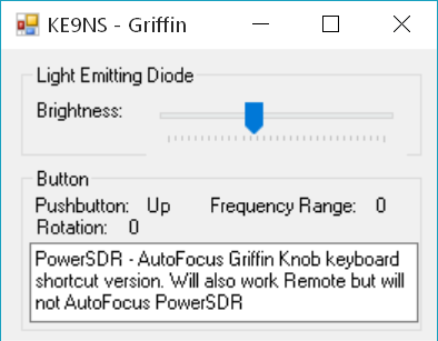
I wrote 3 programs (below) that Force the Griffin Powermate Knob to send Frequency change commands to PowerSDR no matter what you doing on your computer:
1) AutoFocuses the PowerSDR window and sends Keyboard Shortcuts AND also allows Remote Knob Operation (but without the AutoFocus)
2) Sends CAT commands to a COM port connected to PowerSDR
3) Same CAT commands, but with a Signal Strength Meter added.
NOTE when using any of these programs:
Do NOTrun the PowerMate program you normally use with the Knob (look for the knob image in your tray). Windows should install the Griffin driver automatically.
1) PowerMate/PowerSDR using keyboard shortcuts (i.e. PowerSDR only)
NOTE:This version now allows remote operation over a "Remote Connection" but does not autofocus the PowerSDR window on your "Remote Connection". BUT, if you are running it locally, it will still auto focus to PowerSDR.
Do NOTrun the PowerMate program you normally use with the Knob (look for the knob image in your tray). Instead download this zip file, unzip the folder and keep the 2 files together. Simply run the .EXE file (but in ADMIN compatability mode). Just minimize to the Tray and leave it running all the time PowerSDR is running. You will need to have .NET 4.0 framework installed.
This will work with the new PowerSDR 2.7.2 ke9ns revisions, BUT you must run "PowerSDR", then run "Ke9ns PowerMate", then its OK to open the DX spotter window. It must be done in that order using this version.
2) PowerMate / Flex Radio CAT commands
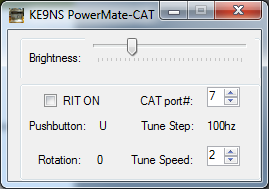
This PowerMate version does not change Window Focus, it simply opens up a COM port that links back to the CAT for your radio.
I use ZZAD/U commands for VFOA with 3 selectable step rates: (100hz,1khz,or 10hz).
I use ZZRF for the RIT function (+/-10hz steps). I could not use ZZRU/ZZRD for RIT because DDUtil gets caught in a loop.
Download this zip file, unzip the folder and keep the 2 files together. Simply run the .EXE file (dont need ADMIN permission). You will need .NET 4.0
The default is COM7 (you can select 1-16). You will need to use a program like "vspMgr" to create virtual COM port pairs (i.e. virtual COM6-COM7 pair), and DDUtil to link 1 side of each COM pair back to your CAT rig. (i.e. set RCP1 in DDUtil to COM6)
3) Flex Radio CAT commands RX Signal (with Powermate)
Download this zip file. This version (again dont run PowerMate Editor) can work with or without the PowerMate (but you still need to install the driver). The meter skin is called Met2.jpg and is replaceable. Just keep the skin in the same folder as the .exe and .dll files. Now the Meter movement is smoother and the needle is smoother.
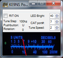
The meter image is my tribute to the TR7.
Below is a short youtube iphone video I took showing the above ke9ns powermate software running.
You can copy the default "Skin" to use as a starting point for creating a new "Skin".
Skins under V2.7.2 or V2.8.0 are found in the following location (Click on the START button and enter the following in the search window): %ProgramData%\FlexRadio Systems\PowerSDR\Skins\
Highlight the "Default 2012" folder and press CTRL C, then CTRL V
You will now have a new Folder called "Default 2012 - copy"
Right click on folder and rename it your call sign (ie. KE9NS)
Navigate into the new FOLDER inside the "Console" folder. These are the files you can change.
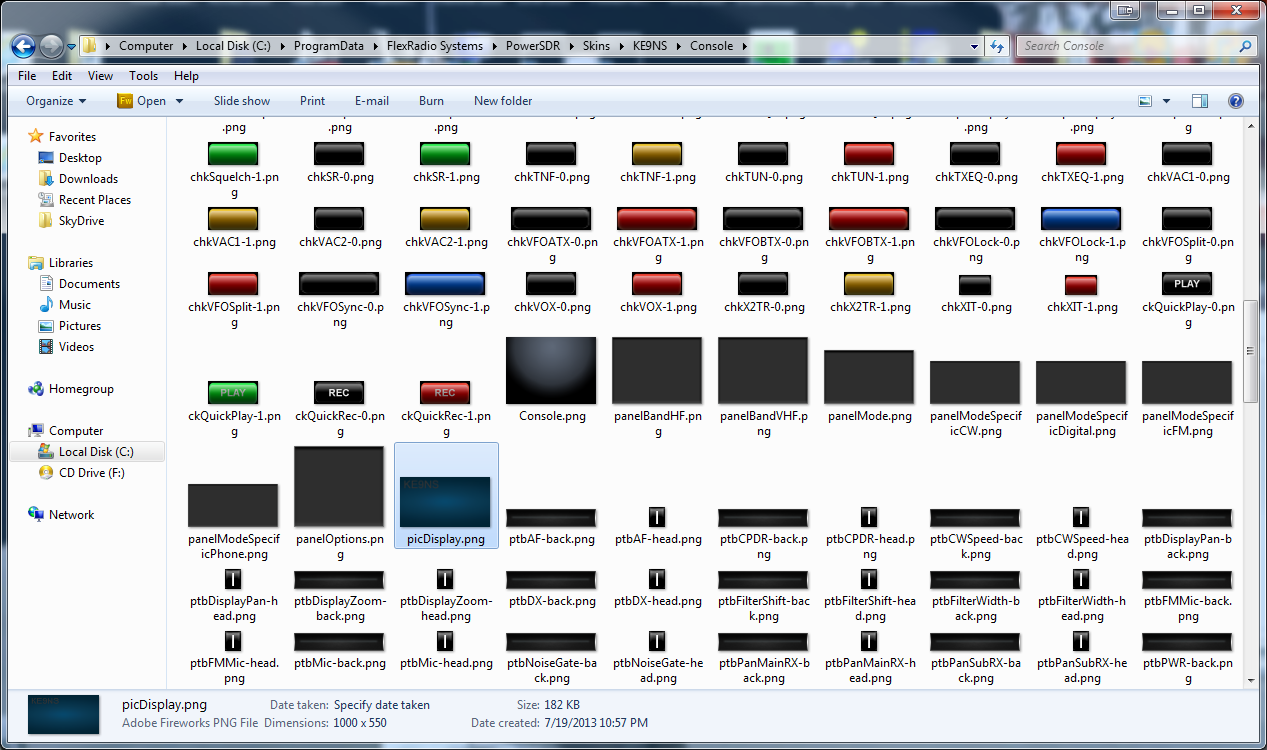
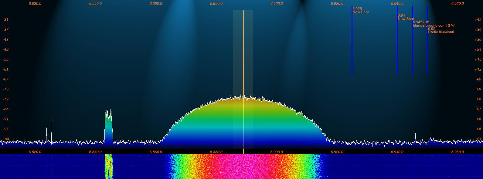
In my KE9NS example I changed the "picDisplay.png" file which is the background of the Panadapter.
Started from scratch with Adobe PhotoShop.
1)
Create a new picDisplay.png file with a canvas of 1000 x 550 (the standard skin is a 100 x 50 image, but that will be too blurry if we add a call sign).
2)
Pick a background color (use the eyedropper tool to pick a color from some other image), and use the paintbucket tool to fill the canvas.
3) Now add a background lighting enhancement, so click on Filter->Render->LIghting Effects->have fun. The image on the left is virtually lit from the bottom right. The image on the right is virtually lit from 3 sources above the skin (like on old radio with light bulbs over the dial).
4) Now add your callsign to the image in the upper left corner. Pick your Font (i used LCDMono) and size (i used 72pt) and Opacity I added a lensflare (Filter->Render-> Lens Flare) just to the callsign.
5) Next, I replaced the slider(s). RX2 sliders are slightly smaller,so there are 2 sizes.
6) Since the slider we are creating is round,and all image formats save files with 4 sides, we need to create a cavnas with on opaque background (i.e. a see through background), it shows up as a checkerboard pattern in Adobe.
7) I found some knob images on the web and scaled them down to fit.
I have now also included a background without the call sign but with a robinson projection.
The slider replacements are slightly larger than the original 20 x 20 and 16 x 16. My Slider(s) are 22 x22 and 19 x 19 (see below)
Click here to download the "Skins" (without my callsign)


![]()
![]()
At this point
go to PowerSDR -> Setup -> Appearance -> and select the new "Skin".
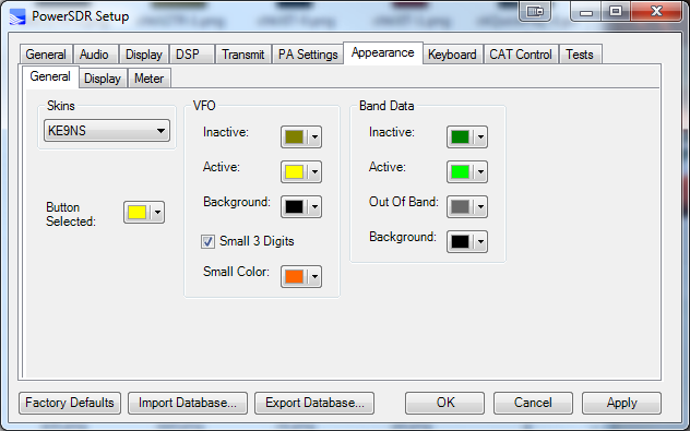
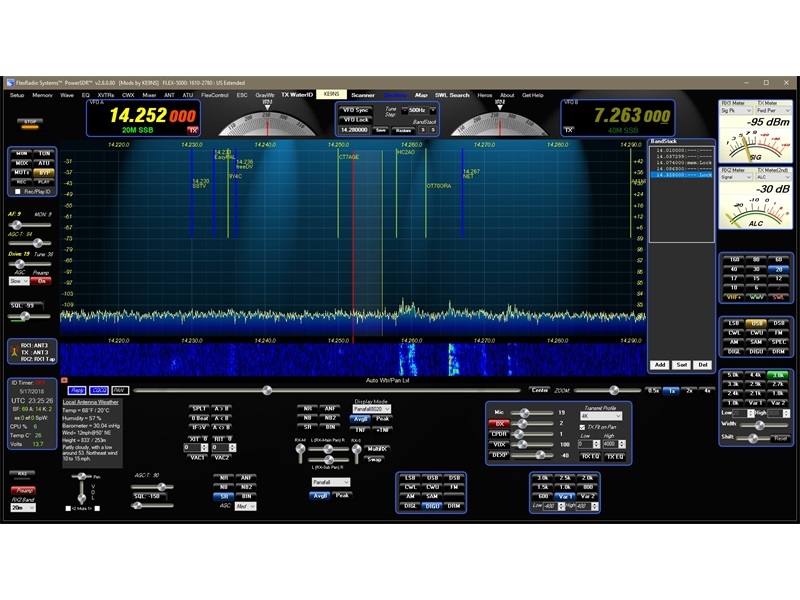
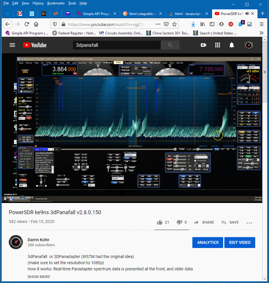
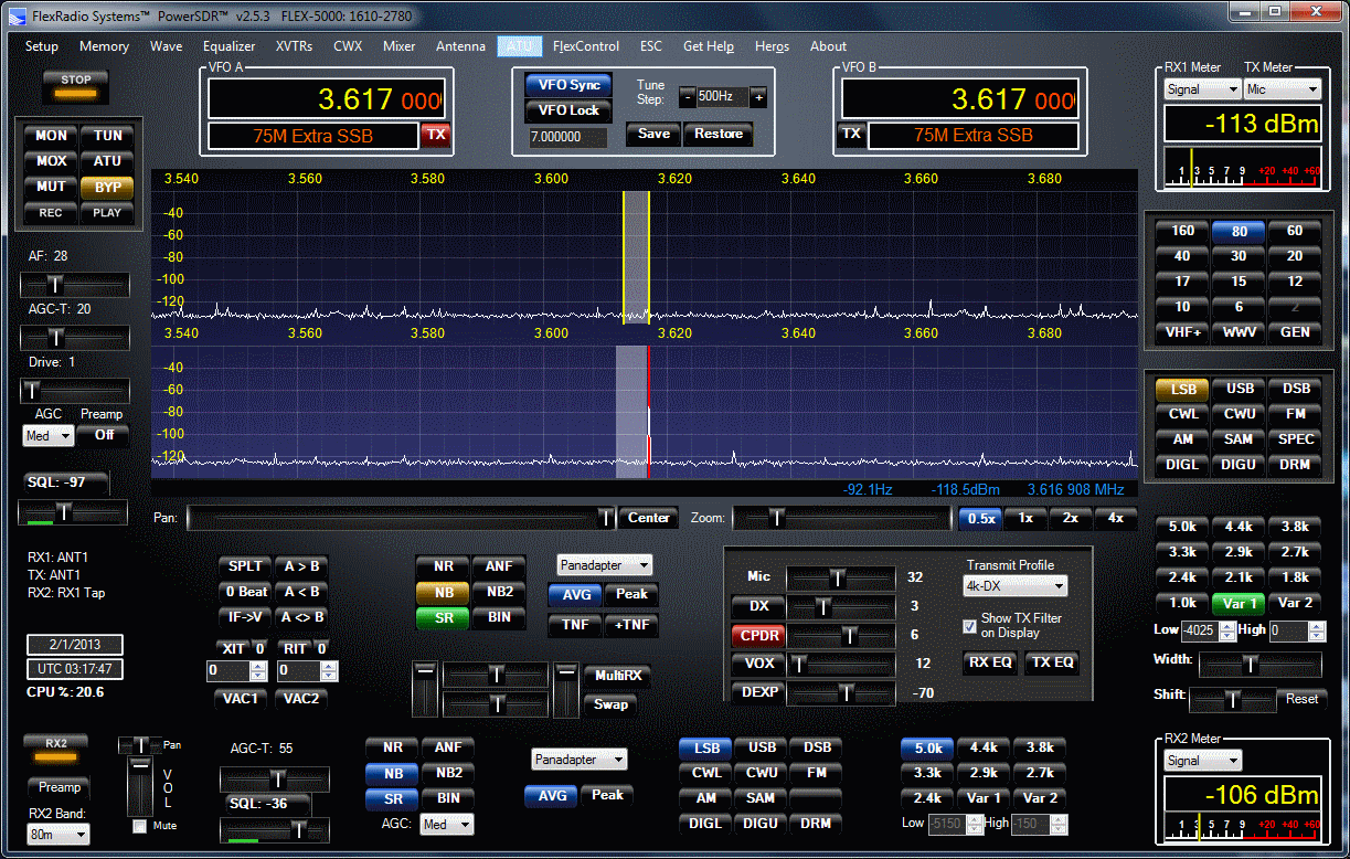
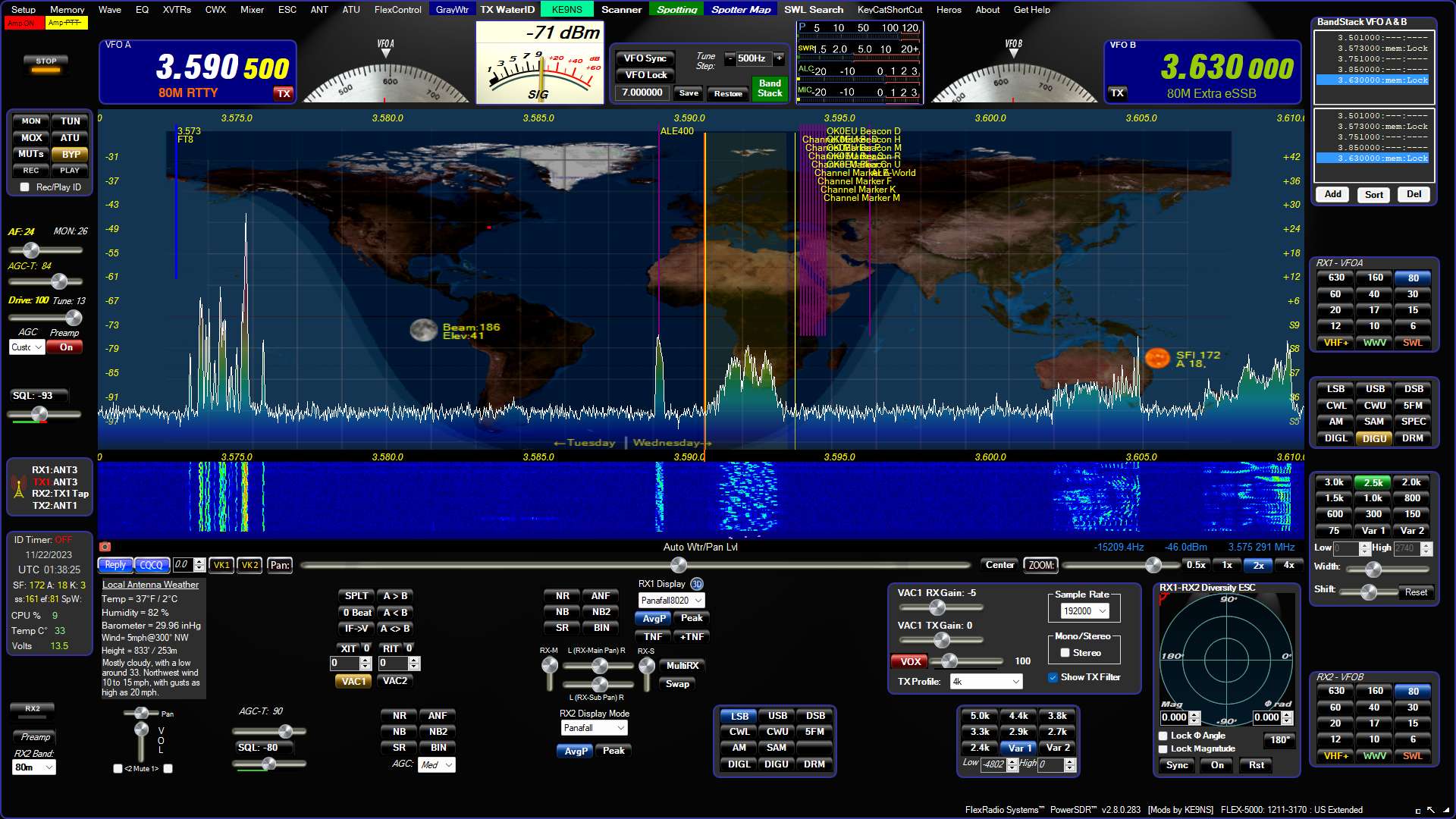
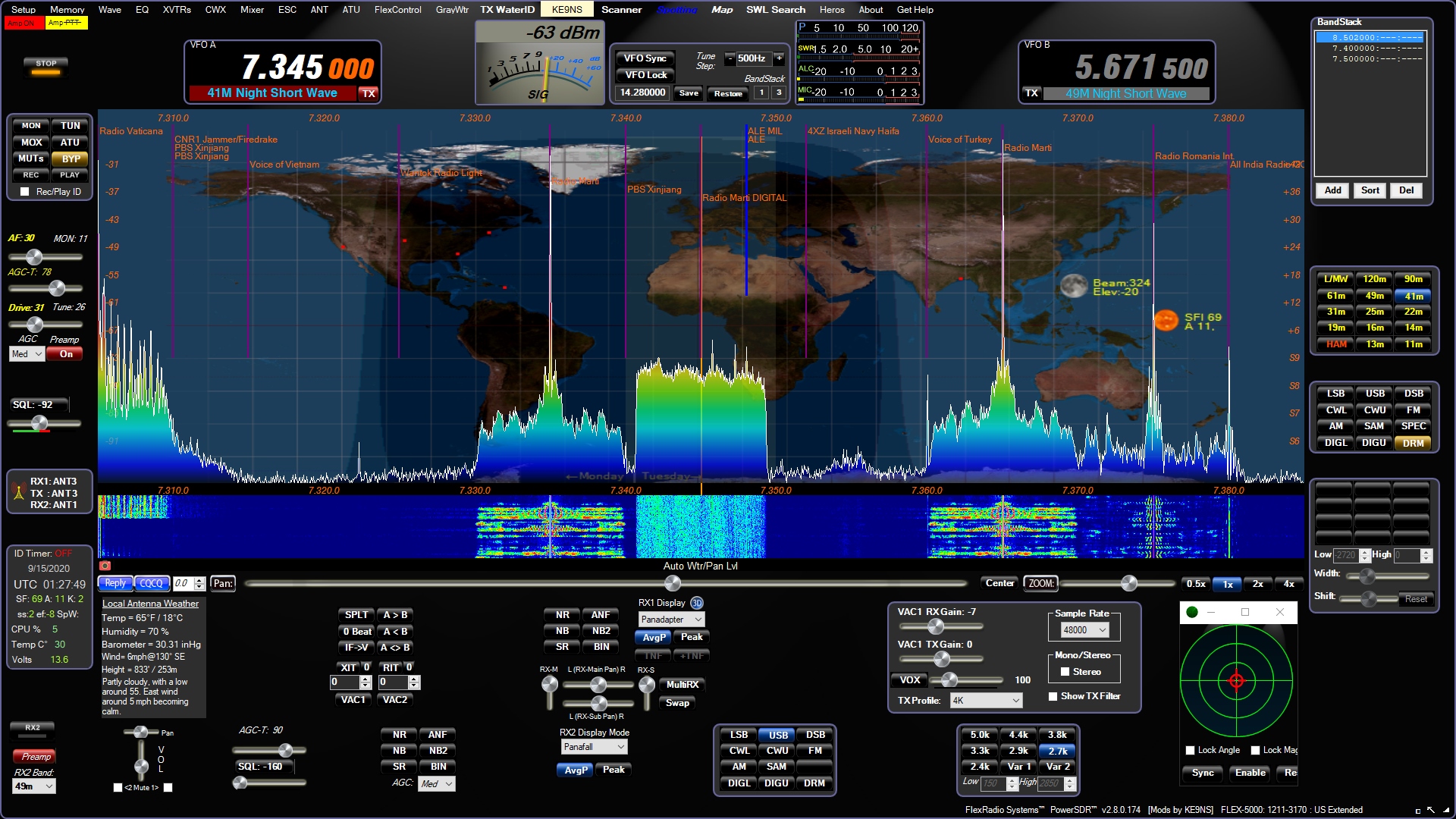
The Panadapter will now look like the photo at the top of this page.
At this point its best to shut down PowerSDR and reboot your computer.
FireWire IEEE 1394 Interface (driver issues) and Thunderbolt option
FireWire (IEEE 1394):
If you are looking for options to add FireWire to a newer mini-PC or laptop or Desktop, scroll down to "FireWire Solutions for mini-PCs and Laptops" for a few options.
(NOTE: Freezing is not generally related to FireWire, but means either your PC is underpowered or you have a bad driver. Search DPC Latency on this website instead)
If your FireWire is crashing (causing a PFN_List_Fault) Blue screen of death:
(1)
You can check on all the items listed below, BUT first as a test, disable all Virus protection (some programs will require fully uninstalled in order to disable). This includes the built in Windows Defender: By disabling the Win10/11 "Real-Time protection" and Win11 "Memory integrity". It has been noted that Windows defender "msmpeng.exe" can cause a large number of "Hard Pagefaults" while running PowerSDR. See if the PFN crashing goes away when you Disable Real-Time protection via windows Defender?
(2)
Make sure your Windows 10/11 Power Plan is set to "High Performance" power plan. Control Panel->Power Plan.
If you dont see a "high performance" listed under Power Plan:
Run "Command Promt" right click"Run as administrator" and copy/paste the following for "High performance":
powercfg -duplicatescheme 8c5e7fda-e8bf-4a96-9a85-a6e23a8c635c
This is for Ultimate performance: copy/paste the following for "Ultimate performance":
powercfg -duplicatescheme e9a42b02-d5df-448d-aa00-03f14749eb61
Both these Power Plans are not for laptop battery usage as they disable all power saving features and keep all CPU cores running, but are needed for Real-Time Audio DSP
(3)
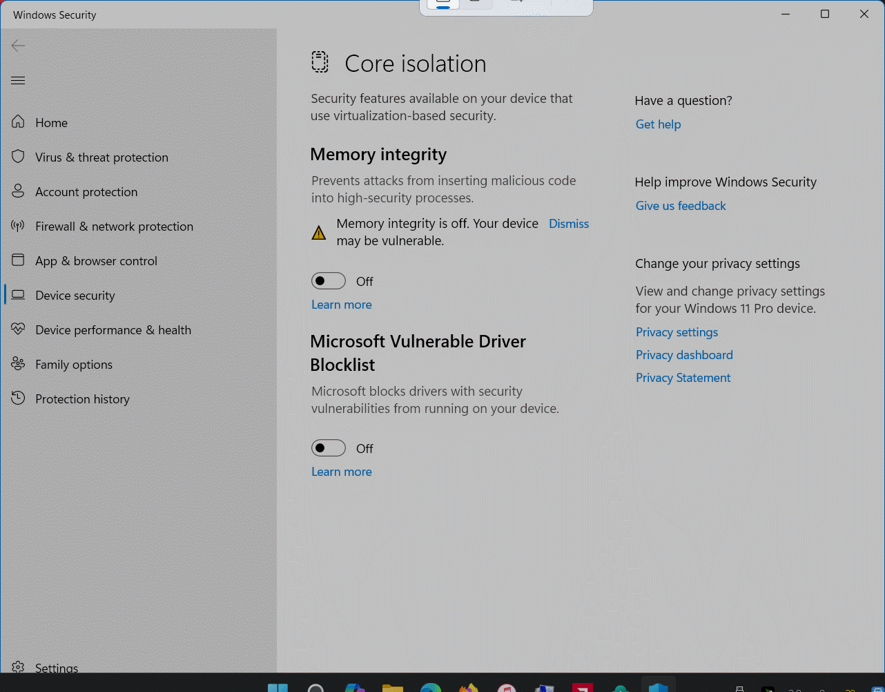
Win11: Disable all Core Isolation features: Memory Integrity and Vulnerable Driver (this is if your motherboard&CPU support this):
(4)
Open CMD prompt (run as Admin) bcdedit /set disabledynamictick yes for reduce possible DPC latency.
(5)
This should not be needed if your Power Plan is set to High performance:
Open Regedit: Computer\HKEY_LOCAL_MACHINE\SYSTEM\CurrentControlSet\Control\Power\PowerSettings\54533251-82be-4824-96c1-47b60b740d00\0cc5b647-c1df-4637-891a-dec35c318583
and set ValueMax and ValueMin both to 0 to prevent windows from shutting down any CPU cores. Or you can download "Parkcontrol" to prevent CPU core parking.
(6)
FireWire requires an IRQ (Interrupt Request) channel. Its best that the IRQ channel selected for your FireWire Card is unique and has no IRQ conficts with other devices on your PC motherboard. Your BIOS selects the IRQ for you.
Newer PC motherboards now use MSI and MSIx (Message signaled interuppts) for their onboad devices, and so usually have plenty of open IRQ available. Somewhat older motherboards support MSI but rely heavily on IRQ for their onboard devices, and so many onboard devices share and IRQ. You may or may not be able to run PowerSDR successfully with a shared FireWire IRQ.
Windows Device Manager->View->Resources by Connection->IRQ
NOTE: Negative IRQ numbers are MSI (Message signalled interrupts, as opposed to the original pin based IRQ). Devices that use MSI are not allowed to have conflicts. Modern PC Motherboard chipsets will have PCIe version 3.0 or better to take full advantage of this. This will leave plenty of room for tranditional IRQ devices.
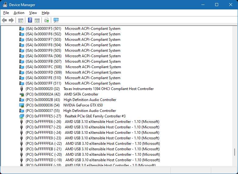
Although windows permits IRQ sharing, your 1394 FireWire card cannot be allowed to share an IRQ.
Windows no longer allows for IRQ manual assignements.
And Modern BIOS configurations will usually NOT allow for manual IRQ assignments.
NOTE: Altering your BIOS is dangerous for the inexperienced, and may cause Windows to become inoperable.
Older BIOS configurations may have a "PnP operating system" checkbox to disable. Modern BIOS configurations may have a ACPI checkbox to disable.
The other possibility is to simply move the 1394 card to another PCIe Slot (Note: Any PCIe slot, large or small will accommodate the 1394 PCIe card).
Also sometimes simply using "Device Manager" to disable and then Re-enable, may cause Windows to assign a new IRQ#.
------------------------------------------------------------------------------------
This procedure (below) is a last resort to free up an IRQ conflict on your FireWire Card:
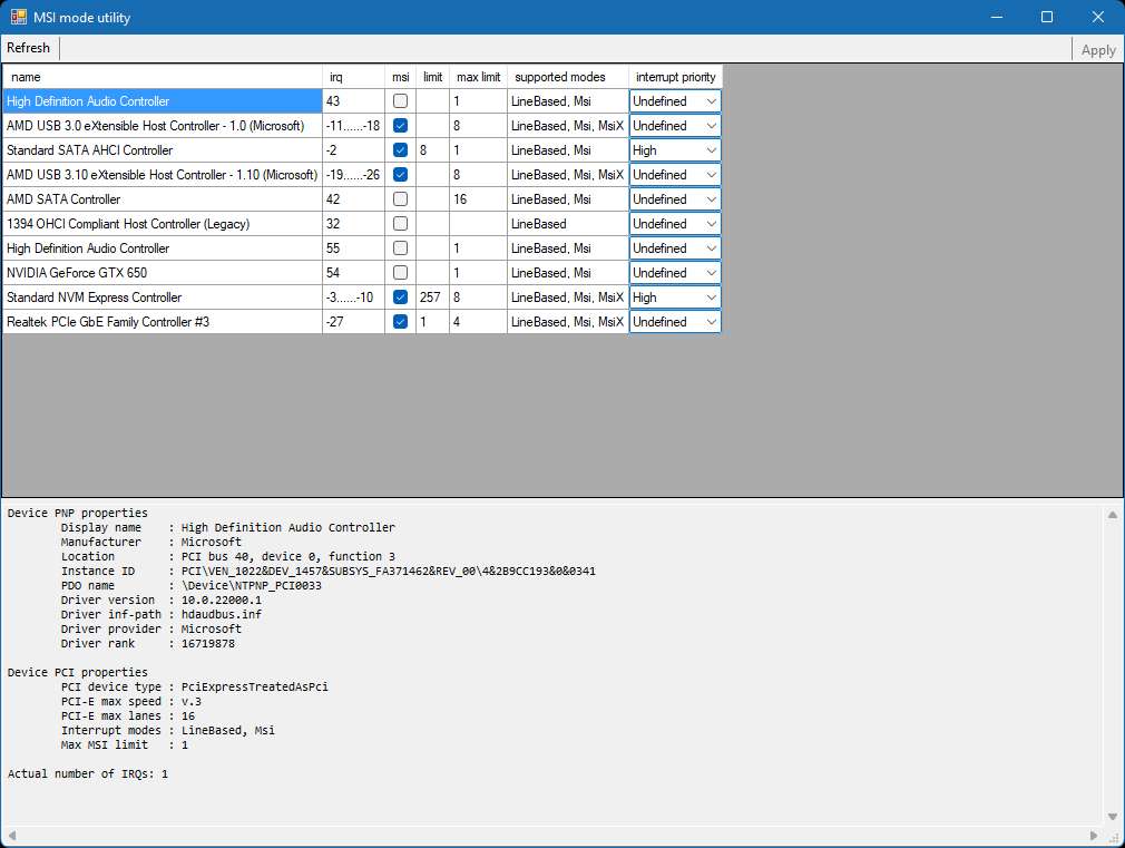
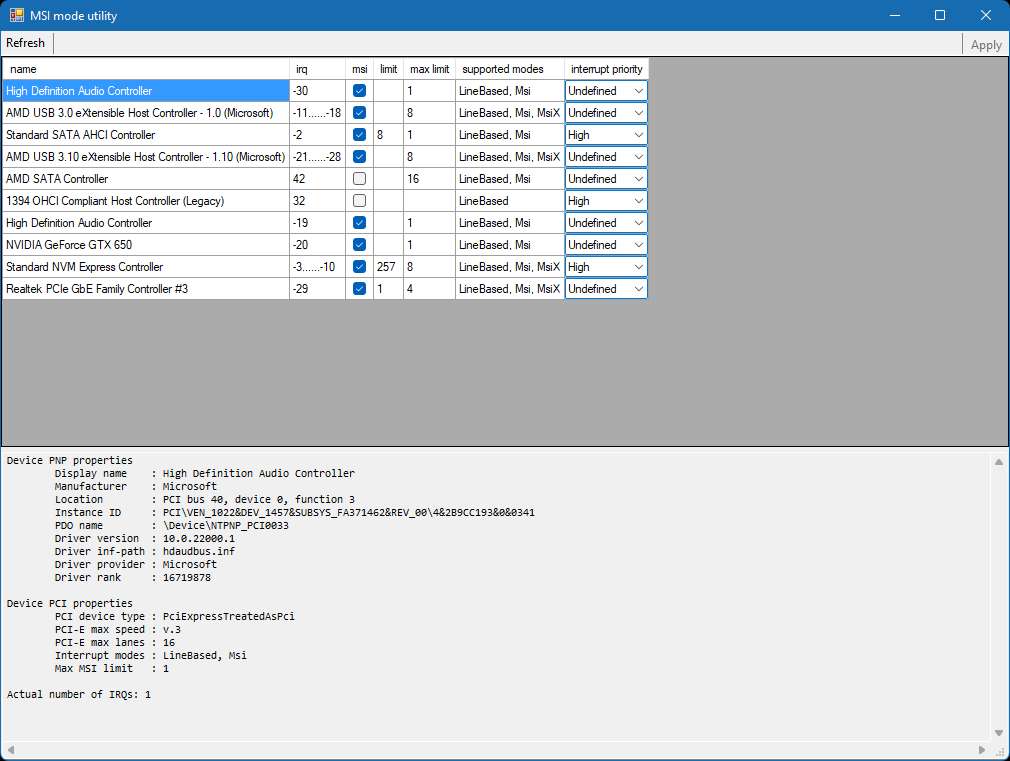
This procedure involves moving PC devices from standard IRQ to MSI (Message Signaled Interrupts). MSI devices are not allowed to have conflicts and show up as negative IRQ values. By Freeing up standard IRQs, this might remove a FireWire Card IRQ conflict. Usually NVIDIA graphics cards can be moved to MSI. Along with Audio devices. Some devices listed as MSI capable will not work properly under MSI and can cause your Windows to no longer boot.
NOTE: This is not for the faint of heart. This procedure has the possibility of bricking your Windows PC. Always make sure you create a fresh "System Restore" point, also go into REGEDIT and make a backup copy to an accessible location (like your desktop). Make absolutely sure to create a USB "Recovery Drive" before attempting any IRQ MSI alterations. This way you should be able to boot the Recovery Drive and restore to a previous Restore point. If you dont see some devices already listed as MSI (no negative IRQ devices), then dont try this as your PC is too old.
MSI_util_v3 This is the direct download from my site, otherwise you can follow the links below incase there is a newer version. Drop it on your Desktop (nothing to install) and run in ADMIN mode
See: https://maxedtech.com/show-devices-by-irq-in-windows/
and See:
https://forums.guru3d.com/threads/windows-line-based-vs-message-signaled-based-interrupts-msi-tool.378044/
This involves altering your Registry to move devices from IRQ to MSI (you can also increase priority levels) using a free program called "MSI_util_v3.exe" that must be run in ADMIN mode. This utility modifies your Registry.
I did this even though my FireWire had no IRQ conflict.
------------------------------------------------------------------------------------
(7)
If your having trouble getting your Flex-3000 or Flex-5000 to connect to your FireWire card, it may be the driver. You can try installing the Win7 based Legacy Driver instead of the default driver.
Download:
Legacy1394 x86/x64 FireWire Driver This version will create a folder:
C:\Program Files (x86)\1394 OHCI Compliant Host Controller (Legacy)
With a x86 and x64 subfolders
If your Windows is x64 It will just place the drivers into the folder: C:\Program Files (x86)\1394 OHCI Compliant Host Controller (Legacy)
But if your Windows is x86 then the folder will be C:\Program Files\1394 OHCI Compliant Host Controller (Legacy)
Go into either x64 or x86 folder (based on what version of Windows your running)
Then right click over the Legacy1394.inf file and select Install
Now when you open device manager and select 1394 FireWire->update driver->Browse my computer->Let me pick from a list, Legacy should now be in the list
x64 Win10 / Win11 PCs may require a "Signed" driver, but these were never signed. You may need to "Disable Driver signing" on you PC to allow switching your 1394 FireWire card over to "legacy"
NOTE: If you are having troubles running a Flex-3000 or Flex-5000 at 192k sample rate, try the Legacy Driver. And change the sample rate only from within PowerSDR: setup->Audio->Primary->Sample Rate
Device manager will list your FireWire card as: IEEE 1394 host controller (Either LSI, TI, or VIA 1394).
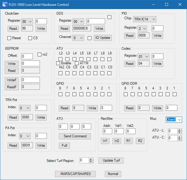
Flexradio.exe app Go into Flexradio app
1) set Operate Mode to "Normal". Click the DPC button to confirm the Firewire connection has low latency. If not, check your PC for un-needed and unused programs. You may need to reinstall the OS for a clean start. High latency will cause very strange audio issues. You will eventually see a few time the computer encountered high latency, hit the Clear button to make sure it doesnt happend that often.
2) Buffer size: Dictated by the PowerSDR -> Setup. So dont try and change it here.
------------------------------------------------------------------------------------
FireWire solutions for mini-PCs and Laptops.
(For those not running a Desktop PC which has a PCIe slot):
Luckily almost all the slots found on newer laptops, and mini-PCs are PCIe based slots with just smaller form factors.
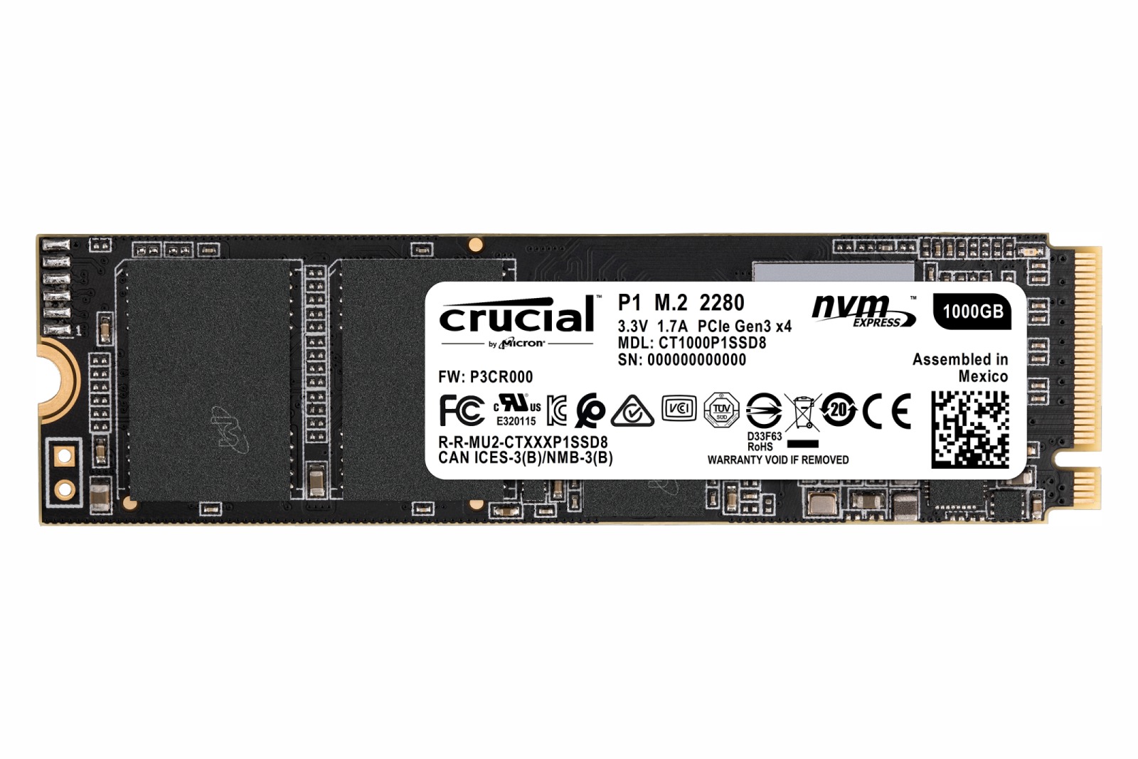
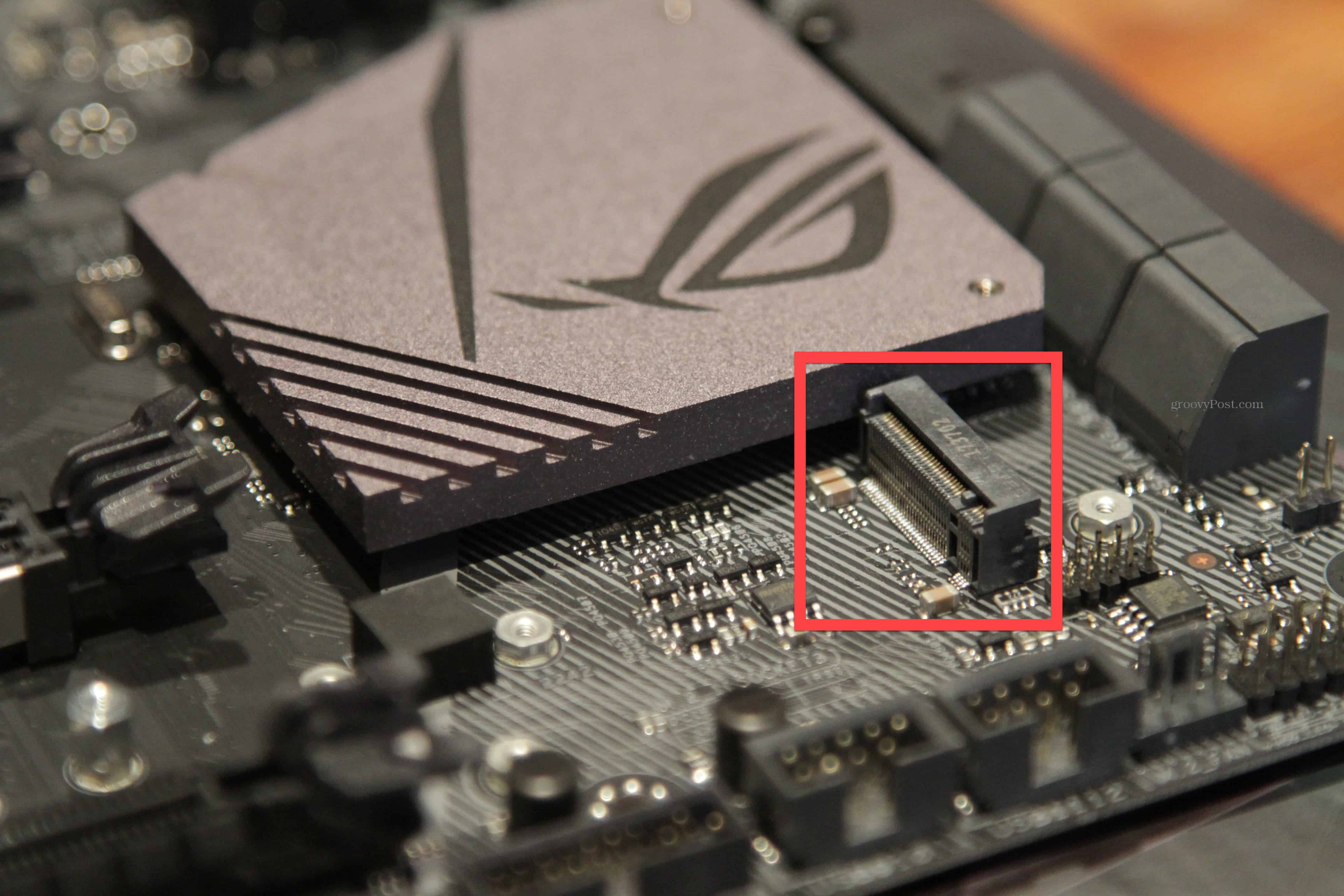
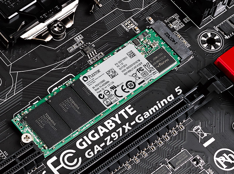
m.2 PCIe slot (used in Mini PCs & new laptops, for wifi/bluetooth):
Its a 4 channel PCIexpress slot in a very small form factor. Its smaller than the original mini PCIe slot, but more capable. Mini-PCs are full blown Windows 11 PCs the size of a Sandwich. I have a Aerofara Tank56, Ryzen (12 logical cores), m.2 SSD, and capable of running 3 FHD monitors. I have tried using the M.2 slot for 1394 FireWire and it works great!
You can buy adapters that convert m.2 PCIe slots to standard PCIe x1 (where you could use a standard 1394 FireWire card).
OR
Convert a m.2 PCIe slot to a Mini PCIe slot and then use an 1394 card (like the StarTech.com LSI board shown below):
------------------------------------------------
Mini PCIe slot (used in mini PCs, and laptops for wifi card):
If you open up your laptop and find a mini PCIe slot (usually used for wi-fi cards), you can buy a 1394 FireWire card like this LSI 1394 miniPCIe card from StarTech.com (PN# MPEX1394B3), and run the cable to the outside of your laptop.
This LSI 1394 chip has worked well across multiple machines. I have yet to find a bad one.
Below showing PowerSDR running a Flex-5000 using the Above LSI miniPCIe 1394 FireWire card plugged into a new Windows 11 x64 Touchscreen 10.1" Embedded fanless Industrial PC. Note 3 mini-PCIe slots: 1) msata SSD, 2) LSI 1394 FireWire card, 3) Intel WiFi & Bluetooth card.
-------------------------------------------
ExpressCard Slot (used in Laptops):
I also use a StarTech.com EC13942A1 1394a FireWire ExpressCard (for my Windows Laptop). It works great.
Above is an 1394 FireWire ExpressCard for Laptop computers with ExpressCard slots (preferably ExpressCard 2.0). ExpressCard is really just PCI Express in a different format
----------------------------------------------------------------------------------
Thunderbolt FireWire
Thunderbolt 2 (Left side), Thunderbolt 3 (Right side in a USB-C form factor). The Thunderbolt indicates that its not just a USB-C connector.
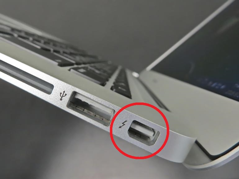
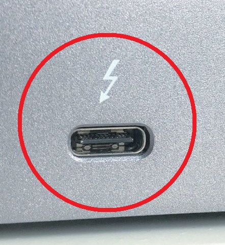
Example shown below:
FireWire on a modern Laptop (Lenovo 20ES P70 ThinkPad)
USB-C Thunderbolt 3 to Thunderbolt 2 (dongle)
Thunderbolt2 to FireWire 1394B (dongle)
FireWire 1394B to 1394A (cable)
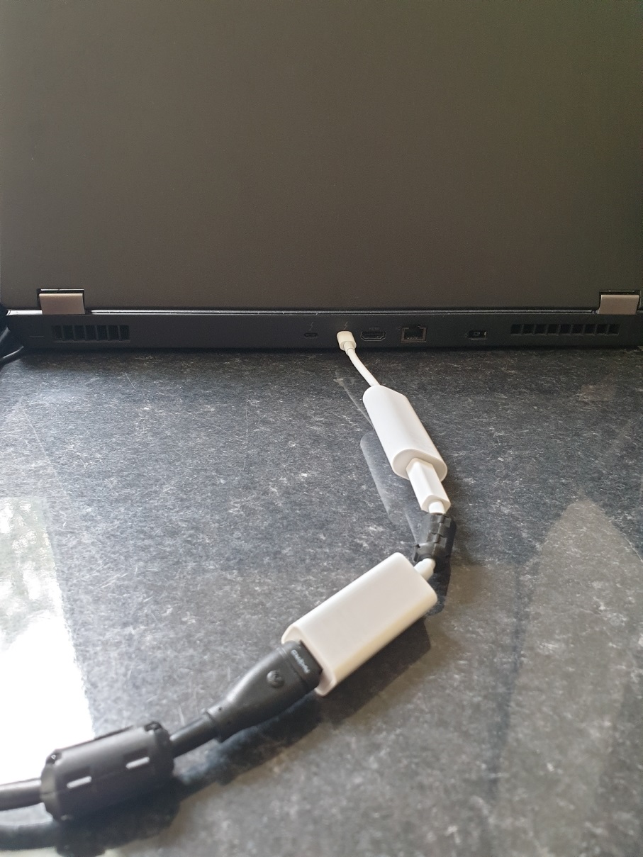
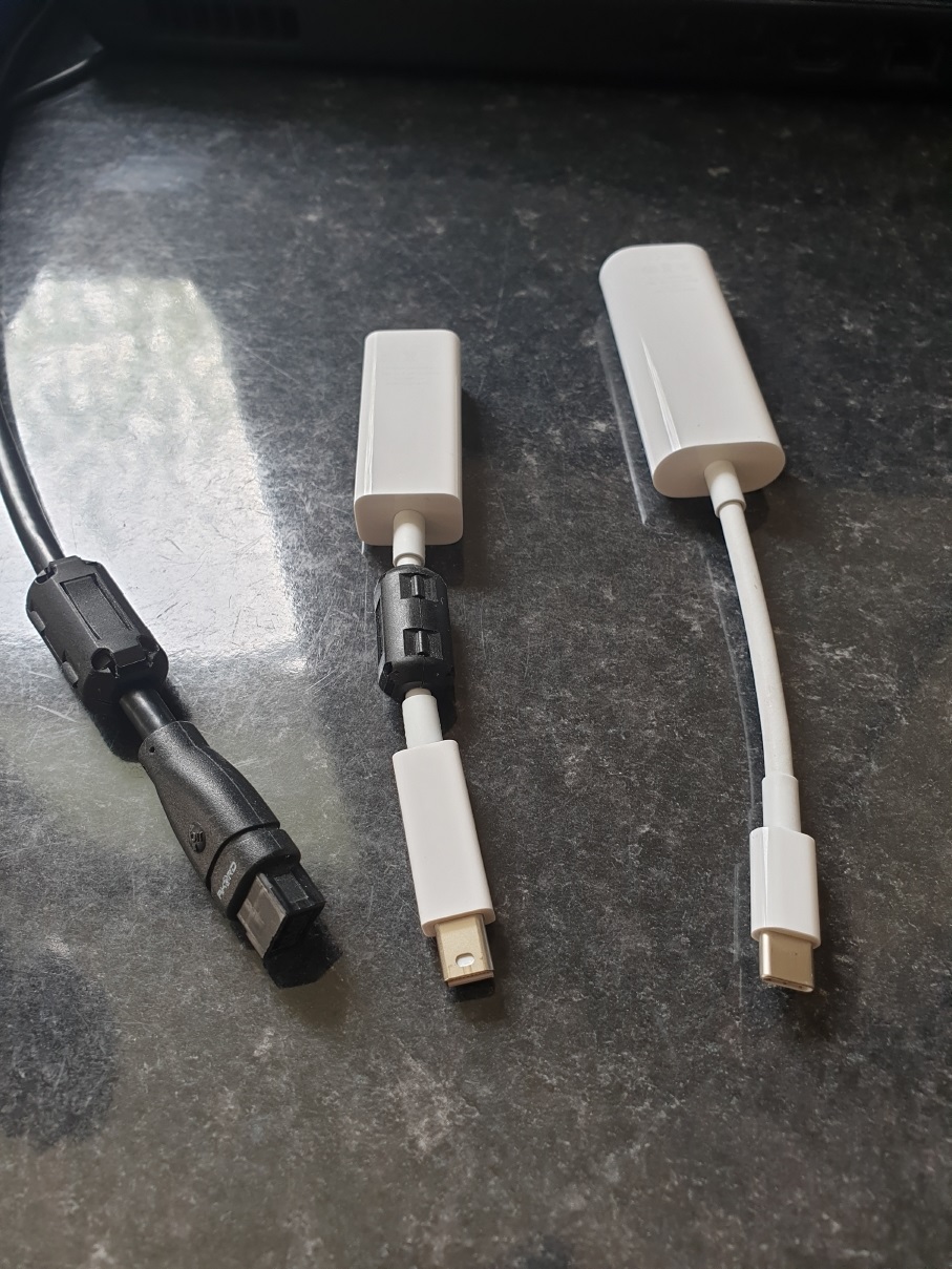
As a LAST LAST resort (see photos above). If you simply cannot get FireWire to work properly on your PC (besides trying another PC), you might consider using "Thunderbolt" (which is backwards compatible with DisplayPort and FireWire).
It has been verifed that this "Thunderbolt" approach works.
First, check if your motherboard already has "Thunderbolt", either as its own Thunderbolt 2 (most likely if you have a mac) connector, or as a USB-C Thunderbolt 3 or 4 (USB-C does not mean its Thunderbolt. It needs to state that it is Thunderbolt 3/4 and USB-C is just its connector).
If you do not have "Thunderbolt" you can purchase a "PCIe x4" card with Thunderbolt on it. That is the card requires a x4 or larger slot (not the x1 slot that most FireWire cards use). They also usually require PCIe 3.0 hardware on your motherboard.
New cards will most likely be Thunderbolt 3 or 4 (which will then require an Thunderbolt 3 to 2 cable.) This has the added benefit in that you gain high speed USB-C plug(s).
Used cards will probably have Thunderbolt 2 & DisplayPort & maybe Thunderbolt 3 (USB-C) connectors.
2) Purchase an Apple Thunderbolt 2 to Firewire adapter. Windows 10/11 should find the drivers for this device.
3) Purchase an Apple Thunderbolt 3 to Thunderbolt 2 Cable (if needed)
43) Purchase a 1394b to 1394a Cable (to interface from the Apple FireWire to the Flex radio)
NOTE: Thunderbolt 3 is not open source and can appear as a USB4 port. If your PC has a USB4 port, it maybe Thunderbolt 3 compatible, and so the above Thunderbolt to FireWire may work using a USB4 port. But Vendors of USB4 do not need to be fully Thunderbolt 3 complient, so your talking a chance.
NOTE: Thunderbolt 3 is now open source and can appear as a USB4 port. If your PC has a USB4 port, it maybe Thunderbolt 3 compatible, and so the above Thunderbolt to FireWire may work using a USB4 port. But Vendors of USB4 do not need to be fully Thunderbolt 3 complient, so your talking a chance.
------------------------------------------------------------------------------------
FireWire Chip Repairs
Repair of the Flex-5000 FireWire Chip (TI TSB41AB2PAPG4) 64pin HTQFP:
If you find your PC does not detect your Flex-5000 when you plug in the FireWire cable and you have determined the fault is in the Flex radio itself. There is a good chance that the TI TSB41AB2 chip has failed AND/OR possibly the DICE chip Applied Technology TCD2210 DICE chip in a 128 pin QFP (not shown)
1394 TSB41AB2 FireWire chip Before and After removal (note the heat sink ground plane connection under the chip)
Kaptan tape used to help protect parts round the chip.
----------------------------------------------------------------------------------------------------------------
NOTES:
NOTE 1: Legacy 1394 OHCI FireWire drivers came about with Win8 when FireWire drivers changed to kernel-mode driver framework (KMDF). The new KMDF 1394 FireWire Drivers sometimes caused issues, prompting the "Legacy" driver (i.e drivers made before KMDF). But Legacy drivers are slower than the current standard drivers based on KMDF.
NOTE 2: Microsoft Win10 (Ver1803) put a limitation on 1394 FireWire related to DMA (Direct Memory Access). FireWire is currently prevented from DMA (i.e. DMA is disabled), in the hopes of preventing threats to Bitlocker. This Windows limitation was then passed along to all versions of Win10 (old and new), and 11. However it does appear that compatability issues have appeared due to this "DMA limitation" put on 1394. There is really no way to Disable this Microsoft Limitation (except a special kernal debug mode). I believe this DMA disable was poorly executed and caused FireWire issues beyond just DMA. I dont believe PowerSDR uses DMA mode, but this maybe some of the cause behind FireWire cards causing a PFN failure and not related to PowerSDR itself.
PowerSDR ESC Noise Cancelling or Signal Enhancing
THE SETUP:
If you have a Flex 5000a with the 2nd receiver option (RX2) and are running PowerSDR 2.7.2 or 2.8.0 you can use the ESC "Enhanced Signal Clarity" feature to reduce noise on the band using a 2nd antenna (RX2). The RX2 antenna needs to pick up the noise as strong or stronger than your main antenna (RX1). I use a vertical for RX2 and a Yagi or G5RV for my main RX1 antenna. My Vertical tends to be very noisy, and my horizontal antennas tend to be very quiet.
HOW IT WORKS:
ESC
"Enhanced Signal Clarity" works by allowing you to sync both RX1 and RX2 receivers together, then allows you to change the phase relationship of RX2 vs RX1. Noise Cancelling happens by moving the RED target around until the noise is subtracted from the real signal. It works very similar to a noise cancelling headphone: detect the noise and inject the same exact signal 180 degrees out of phase to cancel it out of the original signal (i.e. Null Forming). A perfect solution would be an RX2 antenna that picks up nothing but noise since its possible to cancel out the real signal as well.
The additional benefit is that you can improve a weak signal as well, by aligning RX1 and RX2 signals to add, rather than subtract.
Below is a short youtube iphone video I took showing how well ESC works for Noise Canelling using a G5RV on RX1 and a Vertical on RX2.
Below is a NEW short video showing ESC in action using my RX1 ANT3=G5RV and a RX2 ANT1=triband yagi:
I found that after you ENABLE the ESC feature, you can turn off RX2 (the RX2 button in the lower left corner of PowerSDR) and the ESC will still work.
PowerSDR remotely from anywhere using:
Easy 2-way bi-directional audio remote desktop using ONLY AnyDesk
AnyDesk
(free) allows for full remote control desktop of PowerSDR, and 1-way hi-fi audio. But did you know that once your logged into your Radio PC, You can use Anydesk on your Radio PC to log back into your Remote PC, and now you have 1-way hi-fi audio in the other direction (i.e. 2-way audio).
Example Setup: "Remote Laptop (with PC headset), and Radio PC connected to a Flex-5000
Anydesk needs to be installed on both Remote Laptop and Radio PC.
NOTE: I installed the free Voicemeeter banana audio drivers on the Radio PC (it is not needed on the Remote laptop side)
NOTE:
This setup work 100% of the time, BUT....
Any changes that are made to PC SOUND, ANYDESK, or PowerSDR, or plugging in any sound devices to your PC, will usually require closing ANYDESK (and possible PowerSDR and your PC) and relaunching it, for this to work.
NOTE:
Personal Use Only:
If you operate AnyDesk over 100 hours within 8 weeks, you may get a notice that your not a personal user. In that case you need to "Whitelist" both your Remote and Home computers. Go to: https://pages.hs.anydesk.com/anydesk-license
and fill out the form 2 times, with 9-digit AnyDesk ID's from both sides of your connection.
Remote PC (1 time setup):
1) AnyDesk on Remote Laptop: Setup Audio "Transmission" = Headset Mic, "Output" = Headset speaker.
2) Remote Laptop Windows "Sound" Playback default = Headset speaker, Recording default = Headset Mic.
3) Log into the Radio PC. The Top line of the AnyDesk window has a Shield. Click on the shield and check "Transmit Sound". (I FORGOT TO INCLUDE THIS IN THE VIDEO)

Radio PC (1 time setup):
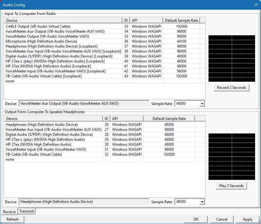
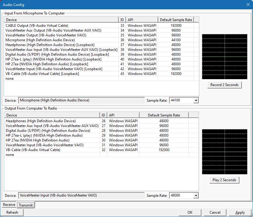
1a) AnyDesk on Radio PC: Setup Audio "Transmission" Voicemeeter Aux Output, "Output" Voicemeeter input.
2a) Radio PC Windows "Sound" Playback default = Voicemeeter Input, Recording default = Voicemeeter Aux Output.
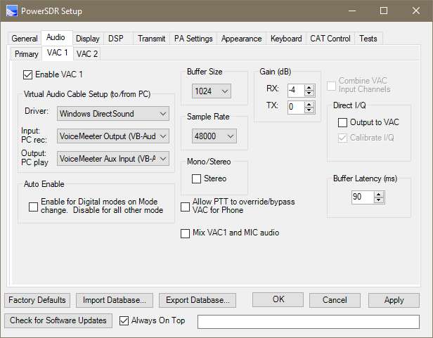
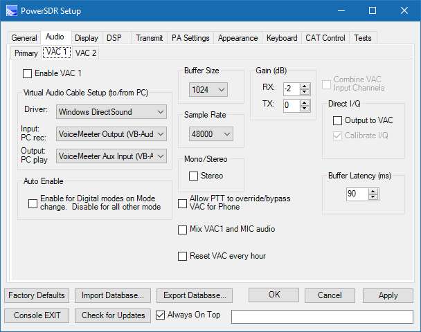
3a) Radio PC "PowerSDR" Set VAC1 DirectSound: IN = Voicemeeter Output, OUT=Voicemeeter Aux Input.
4a) Log into the your Remote Laptop. The Top line of the AnyDesk window has a Shield. Click on the shield and check "Transmit Sound". (I FORGOT TO INCLUDE THIS IN THE VIDEO) 
Operation (Sitting in front of your Remote Laptop):
1) Remote Laptop: Anydesk Log into your Radio PC.
2) Launch PowerSDR on your Radio PC and Activate VAC1. You should be able to see PowerSDR and hear PowerSDR audio on your Remote Laptop.
3) Viewing your RADIO PC Desktop, Run a new instance of Anydesk from your RADIO PC, and Log into your Remote Laptop.
4) Click Accept button of the Anydesk Chat window that pops up on your Remote Laptop. You can minimize this Chat window.
5) Viewing your RADIO PC Desktop, you will now see a small window appear showing your Remote Laptop. Minimize this small window (BUT DO NOT CLOSE OR END IT).
6) Click on the PowerSDR MUX button. You should now have Mic audio back to PowerSDR. Setup->General->Hardware Config->SpaceBar Latch ON/OFF. This will allow you to use the Spacebar to PTT the radio.
What if everyting is setup correctly but you cannot hear Audio or your MIC is not working:
If you cannot hear or the mic does not function, you may need to close both Anydesk connections and reboot 1 or both computers. Also, You may need to open windows SOUND and go into the default Recording device -> Levels tab(on both computers) and make sure the MIC is not muted internally (if you see a red circle with a line through it over the speaker icon). And always recheck the AnyDesk Shield to make sure "Transmit Audio" is checked ON
PowerSDR VAC1 & VAC2 (Virtual Audio Cable)
VAC1 and VAC2 allow you to connect PowerSDR Audio In/Out to your PC without using real analog cables.
If you want to use your PC as a MIC and Speaker for your Flex Radio, select VAC1 as follows:
Driver: DirectSound Driver (you can set the buffer latency down to 90 msec on a fast PC)
Input:
Primary Sound Capture Driver
Output: Primary Sound Driver
Then in Windows Control Panel->Sound, Make sure the Playback and Recording devices match your Speaker and Mic and make sure the Sample Rates match
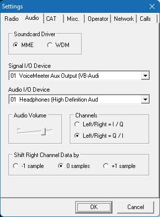
If you want to connect Digital Mode programs on your PC to PowerSDR (like FLDIGI, MIXW, WSJT-X, MMSSTV, NAVTEX, "DREAM", MULTIPSK, SIGMIRA, "SORCERER", PC-ALE, FREEDV, YADD, CWSkimmer, RMS Express, PC-HFDL),
Download and install "VoiceMeeter Banana". It includes drivers for MME, DirectSound, and WDM-KS.
You dont need to run VoiceMeeter Banana, just install it to get the drivers.
Think of a virtual audio channel as a single RCA cable, one end is the Input, the other end is the output. And the AUX cable is a second RCA cable.
VoiceMeeter Banana Drivers install into your PC SOUND Playback and Recording devices as follows:
PLAYBACK
"VoiceMeeter Input VAIO"
"VoiceMeeter Aux Input VAIO"
and
RECORDING
"VoiceMeeter Output VAIO"
"VoiceMeeter AUX Output VAIO"
These VM devices work like a physical Audio Cable with 2 ends (but audio only goes in Input end):
VoiceMeeter Output <- VoiceMeeter Input
VoiceMeeter Aux Output <- VoiceMeeter Aux Input
-------------------------------------------------------------------------------------------------------
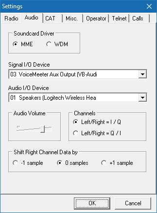
SO... Below you can see my setup:
PowerSDR IN = "VoiceMeeter Output VAIO"
PowerSDR OUT = "VoiceMeeter Aux Input VAIO"
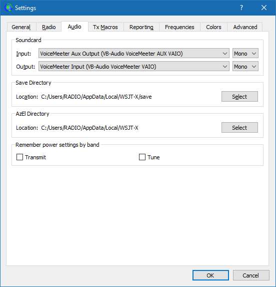
For your PC Digital Mode Program (like WSJT-X) you would select the reverse:
WSJT-X IN = "VoiceMeeter Aux Output VAIO"
WSJT-X OUT = "VoiceMeeter Input VAIO"
USING VAC: Because of Sample Rate (SR) up & down conversion between the Radio itself and VAC1, its best if you use 48khz SR for VAC1 & 2. This is because its a perfect multiple of 192 and 96khz SR.
You must also set the SR for your Virtual audio cables to 2 channel 16bit 48khz (for both Playback and Recording VAC cables (see Windows->Control Panel->Sound).
Failure to do so, will most likely result in buffer lag, which will cause Digital mode PC programs (like WSJT-X, FLDIGI) to not work correctly. If you do notice a lag in VAC audio, check all your Sample Rates to make sure they are ALL set to 2 channel 16bit 48khz.
I use 48000 Sample Rate, but some PC program prefer other values. Make sure Control Panel -> Sounds (Playback and Recording) have matching Sample Rates.
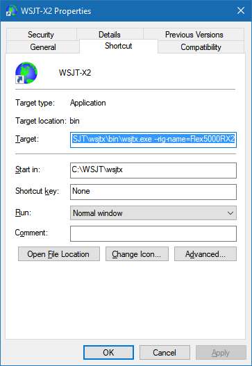
WSJT-X:
This a matching setup to my PowerSDR and DDUtil (note: your COM port pair numbers will probably be different from my setup)
AUDIO MIXER:
If you want to be able to MIX PC audio with your Radio Microphone audio,
Uncheck the "Allow PTT to override" box and Check the "Mix VAC1 and Mic audio" box
Then right click on the windows Speaker Icon (in the tray)->Open Sound Settings, and set the Playback device to "VoiceMeeter Input"
Now: when you PTT your Radio, you can Talk and play PC audio out the Flex Radio
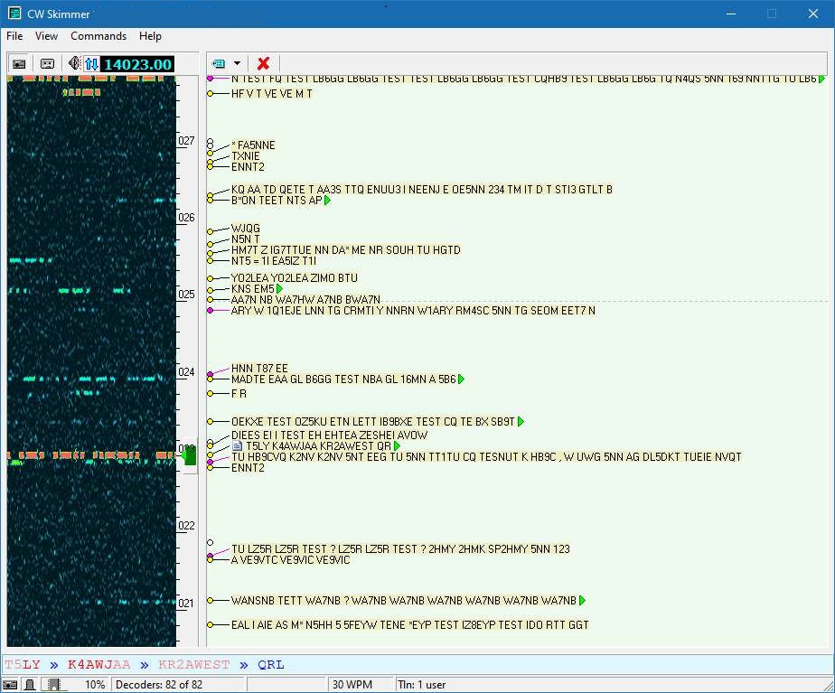
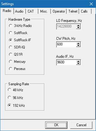
CW Skimmer:
Check the Direct I/Q BOX, when using CWSkimmer, since it requires I/Q audio and be sure to use only DIGIU mode
-------------------------------------------------------------------------------------------------------------------------------
WDM-KS Drivers(Windows Driver Mode - Kernal Streaming)
Windows "WDM-KS" (Windows Driver Mode - Kernal Streaming).
WDM-KS allows for a very low audio Latency. As low as 15 to 20mSec (similar to ASIO).
If you cannot find a suitable WDM-KS Driver, download the free "Voice Meeter Banana" program. You do not need to use the Audio PC program, install it just for the drivers.
WARNING: WDM-KS drivers are can cause crash issues (DirectSound is the safer alternative). With WDM-KS only 1 device can use a WDM-KS device at 1 time, so If you accidently try to open a 2nd PC program using a WDM-KS driver, the driver will crash, forcing you to reboot your PC.
Also the windows Control panel->Sound does not show WDM-KS drivers.
But you can see which devices have WDM-KS drivers in PowerSDR when you select WDM-KS as the driver and check INPUT and OUTPUT devices.
CAT & Virtual COM (serial) Port
PC programs can communicate with the FLEX via CAT commands (which is just a serial COM port). Since there is no COM port on the Flex radio, you must use Virtual COM ports.
Think of a virtual CAT/COM port pair as both ends of a single RS232 Cable (each end of the cable needs to have its own COM port#)
For 32bit x86 installations:
1) Free Download and install SetupVSPE.msi (Eterlogic)
2)
Run the VSPE program
3) Click DEVICE->CREATE->PAIR->NEXT
4) Let it create the pair using the next 2 available COM ports
5) Minimize the VSPE program (to the task bar)
For 64bit x64 installations:
Download VspMgr by k5FR (see"Other Software" link on my page to download) or COM0COM
(NOTE: for VspMgr run only in ADMIN and XP SP3 compatibility mode)
Notice I created a virtual pair COM6<->COM7 (used just for older PC programs that need a seperate PTT COM port). I advise against it since only 1 PC program can use it at a time. COM8<>COM9 for FLDIGI, COM18<>COM19 for WSJT-X. COM14<>COM15 for my logging program. You can use any COM numbers as long as they do no conflict with built in COM port numbers.
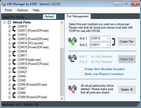
In This case COM18<>COM19 is for WSJT-X:
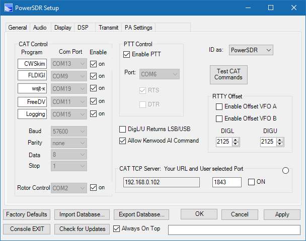
NOTE: I use COM6 for PTT, so only 1 PC digital program can be setup to use COM5 as a PTT at the same time (it does not multiplex), so its best to use CAT to do PTT instead.
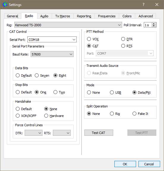
WSJT-X:
use "Kenwood TS-2000" as the Rig as "FlexRadio PowerSDR" as the Rig has issues
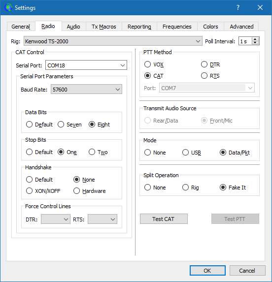
Below is a short youtube iphone video I took showing how to create multiple Virtual COM Port pairs:
Antenna Rotor Control:
If you have a Hygain compatible rotor control, you can now use PowerSDR itself to control your rotor.
For all other rotor controls you must use DDUtil as the mddle man.
This is my example setup:
I have a real COM1 on my PC
I have a bunch of virtual pairs as follows:
COM4<>COM5
COM6<>COM7
COM8<>COM9
COM10<>COM11
COM12<>COM13
COM14<>COM15
COM16 <> COM17
COM18<>COM19
-----------------------------------------------------
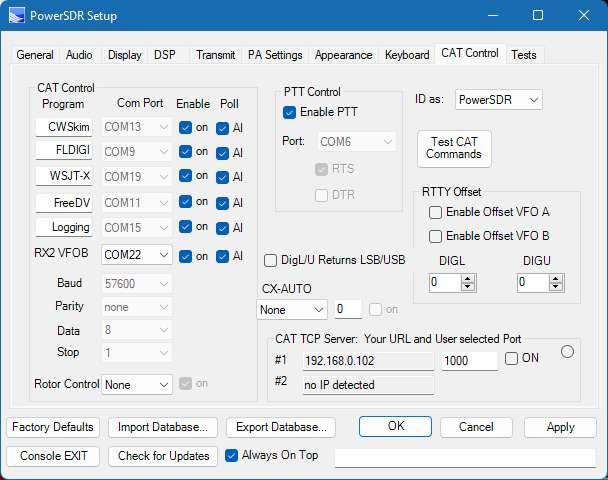
PSDR->setup->Cat control->CAT port COM4
PSDR->setup->Cat Control->Rotor port COM16
----------------------------------------------------------
This just sets up the standard CAT link to PowerSDR
DDUTIL->setup->Features->Legacy->COM5
DDUTIL->setup->ports->RCP1->COM9
DDUTIL->setup->ports->RCP2->COM11
--------------------------------------------------------------
DDUTIL->setup->AntRtr->
check box: Model Hygain for Rotor 1
Set Rotor to COM1 and the correct Baud for your rotor
Check Enable (which opens up a rotor direction panel)
to test, you should now be able to enter an angle into this rotor panel, and move your rotor.
------------------------------------------------------------------
Now This is the Rotor setup link back to PowerSDR:
DDUTIL->setup->ports->RCP1->Rotor Port->COM17 (same row as RCP1 COM9 from above)
Now when you click on the "angle" part of a line in the DX spotter screen
PowerSDR will send an hygain command from COM16 to COM17
DDUTIL will relay the Antenna direction command from COM17 to COM1
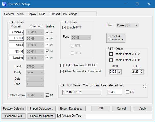
N1MM+ CW using COM ports:
You dont need Virtual audio cables, but Virtual COM ports for CW operation from N1MM+
Below is the CAT setup in PowerSDR:
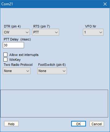
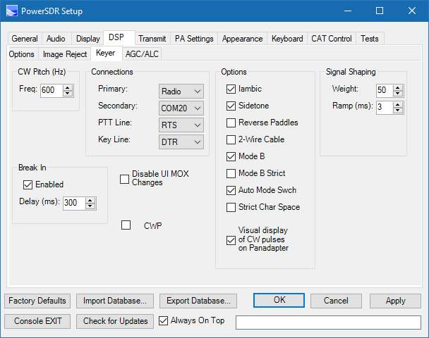
Below is the DSP->keyer (CW) COM setup in PowerSDR:
Below I use COM10 <>COM11 (powerSDR side), and
COM20 <> COM21 (powerSDR side).
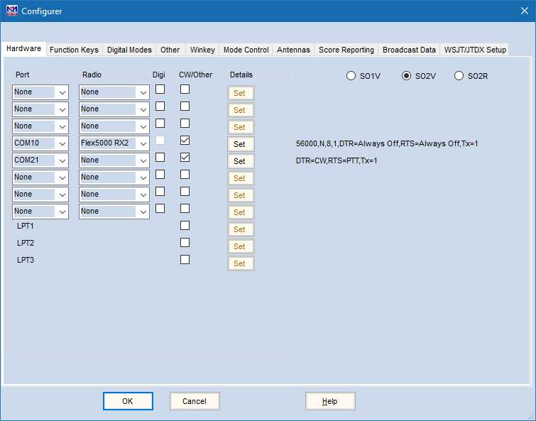
Below is the "Set" for COM10:
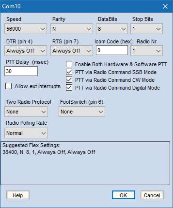
This config allows N1MM to transmit CW. PowerSDR must be in CW mode.
Below is the PowerSDR configuration for N1MM. Select a Port value that your not using in any other PC program: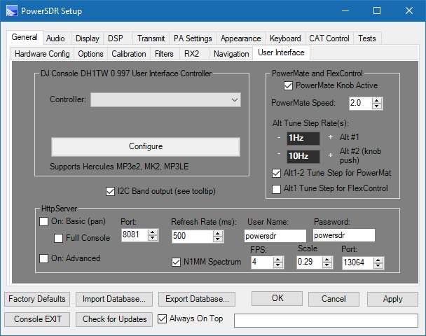
In N1MM+ click on Window and select Spectrum Display:
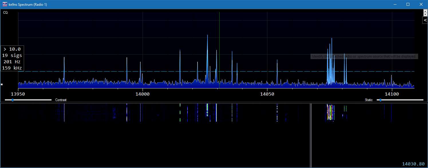
Right Click on the Spectrum and select Spectrum source as the local IP address and Port you selected in PowerSDR, and save it.
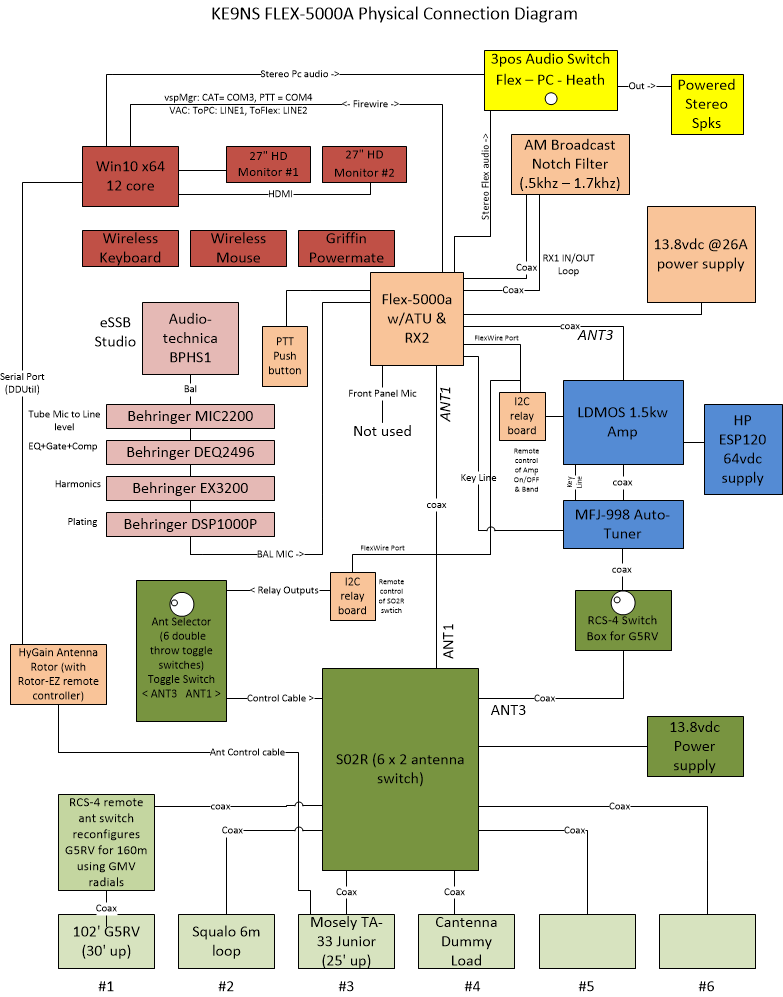
Flex 5000 Station Setup (click to enlarge)
NOTE1: This setup permits ANT3 use the Linear AMP, and RX2 can either tap the same ANT3 or a different ANT1
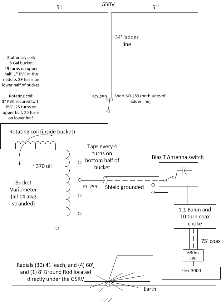
Note2: The G5RV has ground radials under it and so can be configured for 160m by a modified RCS-4 coax switch box (see Antennas section of my web site)
Note3: SO2R: Single Operator and 2 Receivers switch box allows any configuration of up to 6 antennas between the 2 Receivers.
-------------------------------------------------------------------------------------------------------
Below:
"ANT3" is RX1 and goes to the Amplifier, that way RX2 can be either "ANT1" or "RX1 Tap"
"RX1 in/out" is for the AM Broadcast filter (aluminum box down and right side)
"Balanced Line" input for the Studio Mic has been converted to a Combo XLR/TRS connector.
"PTT IN" goes to a Hand Held Push Button on the desk when using the Studio Mic
"PWR-SPKR" goes to a powered Stereo speakers (with Sub-Woofer) and Desk Volume control
"TX3" jack is used to key the Amplifier (not shown)
"FireWire" cable directly to the PC with multiple ferrites on both ends of 6' cable (not shown)
Also not shown is a full coax choke (with ferrites) between the Amplifier and the Ext Ant Tuner, and another coax choke between the Flex Ant3 and the Amplifier.
General PowerSDR Settings for max operation
PowerSDR.exe app Go into PowerSDR app and click on "Setup".
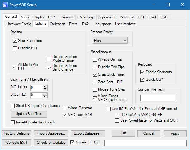
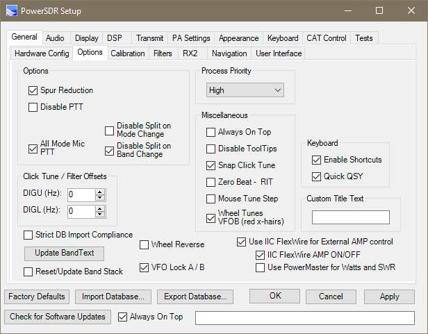
1) General->Options settings
Process Priority to "HIGH" or "REALTIME" (if you have a really fast computer). REALTIME can sometimes cause strange behavior if your computer doesnt have the horsepower.
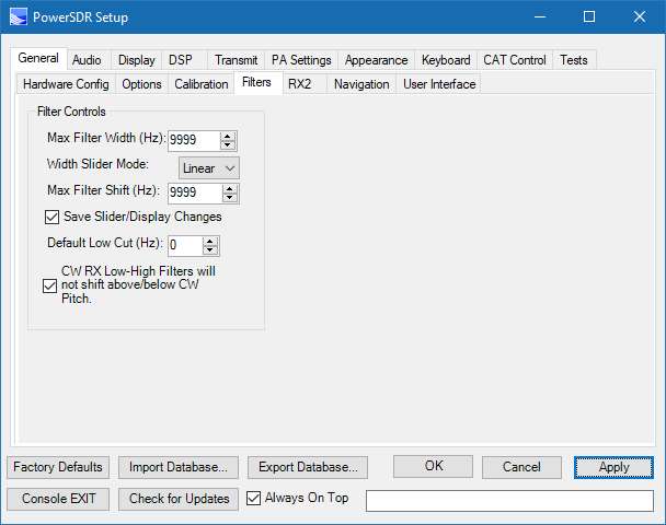
2) General->Filters: reset filters for 9999hz
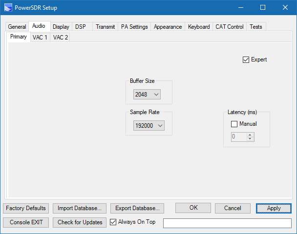
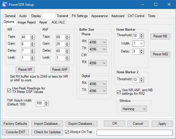
3) Audio: Primary Buffer (lowest possible, but with no sound output issues) 1024 works, but NR and ANF dont work well. Set to 2048
4)
Sample Rate: 192000 (better audio and larger Panadapter window)
Mic Boost = ON, because we need to turn the MIXER MIC input down half way. (this arrangement seems to work better)
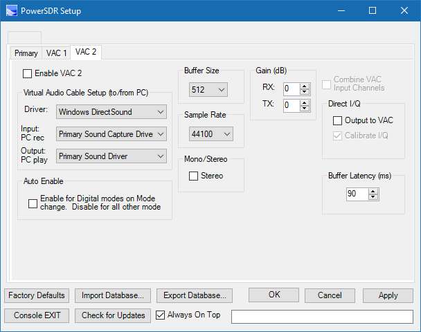
5) Audio: VAC use for digital modes, or remote operation modes. The image is VAC1 using Voicemeeter Banana software (Free). VAC1 is used for digital modes. VAC2 is used for remote listening.
7)
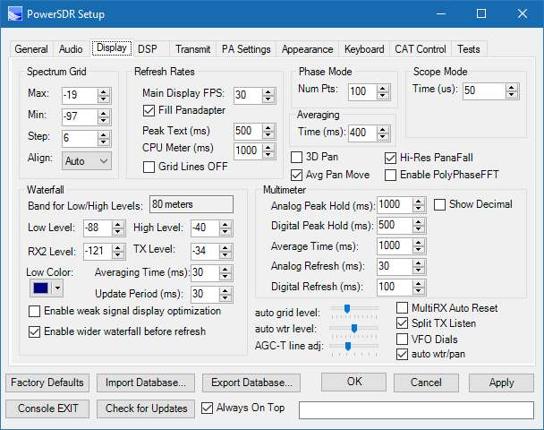
Display: Update Period: 20-30ms (keeps your waterfull up to date quickly when you change frequencies, but higher CPU usage
8) Display: Low Level - High Level: adjust per antenna and band for a slight blue color in the background with no signal.
9)
DSP: Options: 4096 Buffer size get you the sharpest filters but more delay. And NR and ANF and NB work better with 2048 or 1024
10)
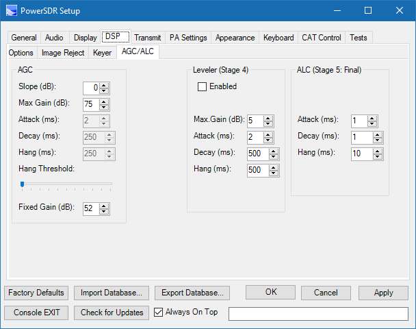
DSP: AGC/ALC: To get more avg talk power, set the Leveler to 5,1,125,170 (higher settings could result in undulations). Set to the ALC to 1,20,170. This allows you to keep your avg ALC up close to 0db but allows peaks to cross over 0db without distortion. Use the 2nd meter "COMBO" to keep an eye on your ALC avg and peak.
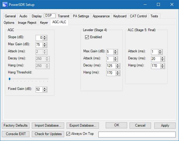
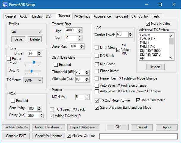
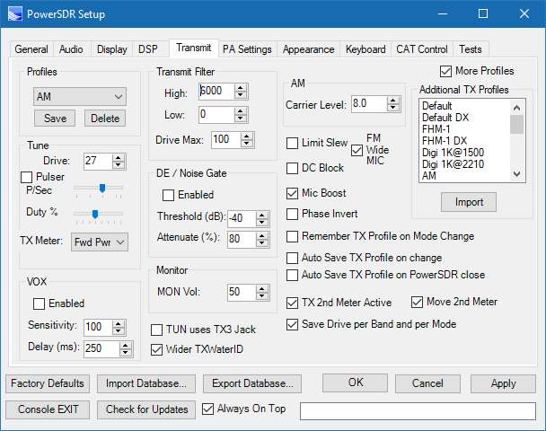
11) For SSB Transmit: save a 4K profile name. HIGH=4000, LOW=100, for eSSB save a 6.5k profile name: HIGH = 6500, LOW=0. Enable the Leverer and use the ALC
12) For AM Transmit: Search down below for AM Mode Operation (proper Setup). This includes disabling the ALC and enabling the CPDR.
13) MIXER:
whatever MIC input you use, move the slider down around half way. But you need to enable the MIC BOOST from Step 4)
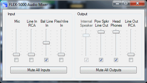
14) MIC: set the MIC gain half way (around 32)
15) You can use the CPDR half way (around 4)
16) You may need to enable MIC BOOST (back on item 4) Settings->Primary->Audio
17) Make sure the TX MIC output meter does not go over 0db
18) Make sure the TX ALC output meter does not go over 0db
Flex 5000 AUDIO eSSB / AM Setup
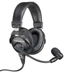
I now use a audio-technica BPHS1 studio headset/ dynamic microphone (40-20,000hz).
Although Condenser microphones are typically superior in sound quality and possess a lower bottom end, there are some downsides. They are typically large, heavy, and very sensitive to noise.
(The "Dynamic microphone" design is very compact & provides much less noise pickup)

MIC2200:
MIC BALANCED IN -> BALANCED OUT TO DEQ2496
Set Gain to get -20db out level
DEQ2496:
MIC2200 BALANCED RIGHT IN -> BALANCED RIGHT OUT EX3200
PEQ: Setting for 3-6khz wide SSB Audio
PEQ: Setting for 10khz AM audio [ie +/- 5khz] or FM modes

(NOTE: Do not add BASS to your audio in AM mode)
(See N9UN's site for full setup details of 2496)
Dynamic Equalizer (used to limit the EQ based on audio level )
DEQ1 (low end volume EQ):
1: - 14, - 48db, 1:8
2: 1.28,-48db, 69.6
3: BP,42.3,4
DEQ2 (mid range volume EQ):
1: -15,-47db,1:10
2: 14.76,-47
db, 62.7
3: BP,408,5
DEQ3 (high end volume EQ):
1: -14, 26db,1:6
2: 0.3, -26db, 45.9
3: BP, 10023,5
Dynamic Expander/Compressor/Limiter
DYN Expander (used to gate background noise):
1: -6, 21db, 1:1.6
2: 2.77, 87.4
LIMIT: 30.6,-11,304
UTILITY: DUAL MONO, Gain offset +10
Switch on back: IN
EX3200:
DEQ 2496 BALANCED LEFT IN -> TRS LEFT OUT ->
INVERT Wires -> TRS RIGHT IN -> BALANCED RIGHT OUT
LEFT : OUT, 2, OUT, IN, 3, 3.3, Full EXCITER, 3, IN (solo OUT),
Surround IN, 2
RIGHT: OUT,2,OUT,IN,6, 4.5,Full ENHANCER,3,IN (solo OUT)
DSP1000P:
EX3200 BALANCED LEFT IN -> BALANCED LEFT OUT PowerSDR
Plate Level 2
----------------------------------------------------------------------------------------------------------------------------------------------------
eSSB Mode Operation (proper setup)
PEQ: (setting for 6khz eSSB audio Audio Technica)
1) Set your Transmit bandwidth to 0hz to 6000hz (low= 0hz, high = 6000hz)
2) Console->Mixer->Input->Mic or Bal Line In->Slider 3/4 of the way up (value = -33)
3) Setup->DSP->AGC/ALC->Leveler-> Gain = 5, Attack = 1, Decay = 125, Hang = 170
4) Setup->DSP->AGC/ALC->ALC-> Attack = 1, Decay = 20, Hang = 170
5) PowerSDR Console->DX = 2 (Compressor works perfect for eSSB mode)
6) Set MIC Level so your ALC and MIC hit 0dB on the meter (its ok to have peaks over 0dB on the PowerSDR meter)
7) Setup->Transmit->Mic Boost ON (if you find you need to keep the mic sliders all the way up)
8) Save your new eSSB transmit Profile
----------------------------------------------------------------------------------------------------------------------------------------------------
AM Mode Operation (proper setup)
PEQ: (setting for 10khz AM audio [ie +/- 5khz] or FM modes Audio Technica)

1) Set your Transmit bandwidth to 0hz to 4000hz, or 5000hz (low=0hz, high=5000hz)
2) Console->Mixer->Input->Mic or Bal Line In->Slider 3/4 of the way up (value = -33)
3) Disable the ALC: Setup->DSP->AGC/ALC->ALC Attack = 1, Decay = 1, Hang = 10
4) Setup->Transmit->AM->Carrier Level = 7 (as a starting point)
5) PowerSDR Console->Drive Level = 100. Adjust Carrier for 25 watts out (for 100 max Radio)
6) PowerSDR Console->CPDR = 5 (Compander works perfect for AM mode)
7) If using an internal or external EQ, remove any bass boost. Boost the high end.
8) Set MIC Level so your audio output on the Panadapter does rise higher than 3/4 of the way to the peak of the Carrier you see on the screen
9) Setup->Transmit->Mic Boost ON (if you find you need to keep the mic sliders all the way up)
10) Save your new AM transmit Profile
100% modulation would be when total PEP is 4 times the carrier. You can go a little higher if the listener is using SAM instead of AM mode.
---------------------------------------------------------------------------------------------------------------------------------------------------------
ADDING AN XLR/TRS Combo Connector
Below you can see where the XLR / TRS Combo Balanced line connector goes. I added shielding over the connector when I was done.
You cant quite get the XLR/TRS Combo connector close enough to the original TRS hole, so there is a small gap between the XLR and panel in the top right of the above picture.
Flex Power Amplifier (PA) and SWR Calibration
This is a Hidden menu function and requires an Array Solutions, Inc. Power Master 1 Calibrated SWR/Watt meter.
Focus on the PowerSDR window and press the following keys: <SHIFT><CNTL> F
!!!!!!!!!!!!WARNING!!!!!!!!!!!!!!!
DO NOT touch anything on this page unless you are willing to brick your radio if you mess up.
DO NOT touch the Input/Ouput side of this window ever.
Calibrations will NOT work correctly unless you are at Factory Defaults.
DO NOT run any other programs on your PC
ALWAYS HIT THE CLEAR ALL BUTTON FIRST on this page.
ONLY SELECT 1 BAND AT A TIME, TO BE SAFE.
Select 1 Band that you would not normally use, just in case you mess up. (like 30m)
PowerMaster:
This zip file contains a folder with the latest PowerMaster 1 firmware, manuals, and Windows PC programs to communicate with the PowerMaster via the serial port.
Click to download PowerMaster ZIP File
"PowerMaster 1" emulation:
PowerSDR sends a special string of hex bytes: 0x02 0x44 0x33 0x03 0x31 0x33 0x13 to force the PowerMaster to transmit over its COM serial port at 38400 8N1 the following string (repeated as fast as you can and forever):
0x02+"D, 29.5, 0.6, 1.32,0;0;0;0;0"+0x03+"BE"
Where (in this example) 29.5 is the watts fwd, 0.6
watts ref, and 1.32 is the SWR.
The (5) 0's are not unused and the "BE" is a ASCII representation of the hex CRC8 byte.
However, PowerSDR looks for the following string (from the COM port repeated as fast as you can and forever): 0x02+"D,00123.4E"+0x13+0x0a
with 00123.4 being the watts detected by your external watt meter (PowerSDR grabs the the 3rd through 10th bytes only). And assuming your external Watt meter needs no correction, the powermaster.txt file correction values should be set to 0 watts.
Setup:
1) To run a PA calibration you need an "Array Solutions PowerMaster 1" meter (original, NOT the Powermaster II )
2) Connect the Serial port to your PC (I use a Serial to USB converter, then set the USB driver to COM1, an unused COM port)
3) Install and run the free Power Master basic PC program to verify you can communicate with your Power Master original.
4) Attach the Power Master coupler to ANT1, then to a 50 ohm DUMMY load capable of over 100 watts.
5) Attach a 25 ohm DUMMY load to ANT2 all by itself. [Take (2) 50 ohm DUMMY loads in parallel to get 25 ohms]. ANT2 is used very briefly during the SWR calibration, so you dont need a large capacity 25 ohm DUMMY load. I just used a high wattage 25 ohm resistor used in RF applications.
6) Export your current database to your Desktop,
you will restore back when your done. (see Settings menu, bottom strip)
7) You must restore the PowerSDR to FACTORY DEFAULTS (see settings menu , bottom strip, left side)
8) You must create a empty text file called: production. (no file extension) in the hidden:
%userprofile%\AppData\Roaming\FlexRadio Systems\ (this is to activate the grayed out buttons on this screen.
9) <CTRL><ALT>S to active the SWR button
10) You must create a powermaster.txt file in the C:\ProgramData\FlexRadio Systems\PowerSDR folder. Click here for a sample file. You insert the gain or loss values for your particular Power Master coupler. (its written in Pen on the HF coupler). But, the Power Master coupler gain/loss is generic for the entire HF band, where the powermaster.txt file breaks it down into each band. You may need to tweek each band value seperately.
The Powermaster coupler correction values will scroll onto the Production PA test right side window. They wont match the values in the powermaster.txt file because they are multipled by the built in PowerSDR gain/loss values for the Flex radios circuits.
Your Ready to start Calibrations:
11) Click Bias button will adjust the Driver and Final Bias values for specific Transmit Idle Amp values. No external equipment needed.
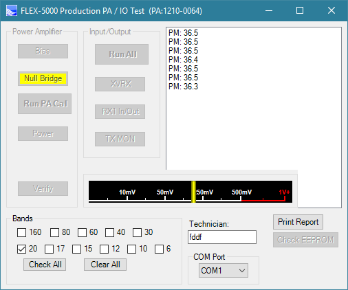
12) Click the Null Bridge button
and a mV scale will pop up next to the Verify button, then manualy adjust the C45 var Cap on the power board inside the Flex-5000 for lowest mV value. The Flex will transmit around 40w to 60w through ANT1
13) Click on the ABORT button when you have the lowest mV reading possible.
14) Click on Clear All button
15) Click on only 1 band to calibrate (an unimportant band to start with)
16) Click on Run PA Cal button. The Flex will calibrate for 1w, 2w, 5w, 10w, 20w, etc. to 100w on ANT1
17) The Flex will then switch in ANT1 and ANT2 to calibrate the SWR for a 2:1 ratio
18) When finished, the PowerSDR will save new EEPROM data to the Flex
(whether the Cal succeeded or failed)
19) I believe that if the Run PA Cal turns Yellow after the calibration of 1 Band; it passed.
Green would be if all bands passed. Red means something failed.
The Verify button will try and output 100w on the selected bands as a pass / fail (I believe a 4watt deviation is allowed to pass). It doesnt need to be done on bands you just did a Run PA Cal on.
Warning:
The Power button (below the Run PA Cal button) causes PowerSDR to crash, dont touch it.
You may lose transmit capability on the band you just attempt to calibrate if the calibration failed to finish properly. You will need to shut down and start over.
If the calibration crashes, you will lose transmit on the band you were calibrating. You will need to shut down the flex and start over.
If the powermaster loses communication with the flex, you will need to shut down the flex and start over.
if you see a NaN for SWR, then the SWR calibration failed. Try again.
If the 100w PA calibration fails, the SWR calibration will likely fail. I believe this is a software glitch.
if the SWR fails, you can manually click the SWR button to run just the SWR test over again.
The calibration may not be able to properly calibrate
a particular band to 100watts. This may be the due to incorrect gain/loss correction values in your powermaster.txt file, or something wrong with the radio. If the Run PA Cal routine finished you will still be able to transmit, you just will not be able to make 100watts at full power. The max watts out will be whatever the routine topped out at.
Below is a short youtube iphone video I took showing how do the PA Calibration.
Class A or Class AB modes
(This is for Flex-5000 only)
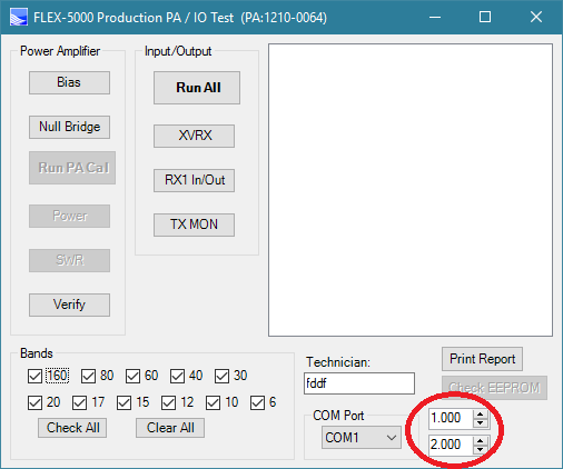
Press <CNTL><ALT> B: Image on right side lower right corner: This allows you to select Class AB or Class A
!!!!!!!!!!!!WARNING!!!!!!!!!!!!!
This was kept hidden because
Class A will get the finals very hot. Limit your output to below 30watts only.
The TOP number is the Driver transistor Bias level multiplier. (Default Class AB = 1)
The Bottom number is the Final transistor Bias multiplier. (Default Class AB = 2)
For "Class AB" operation: Driver = 1, Final = 2, now click the "Bias" button, to re-adjust PA Bias for Class AB.
For "Class A" operation: Driver = 2, Final = 4, now click the "Bias" button to re-adjust PA Bias for Class A.
The PA of the Flex-5000 is a PUSH-PULL MOSFET circuit, designed for Class AB operation where 1 MOSFET is Biased to operate mostly in the Positive region of the AC signal (>180deg), and the other MOSFET is Biased to operate mostly in the Negative region of the AC signal (>180deg). Together they cover the 360deg of AC signal. This configuration increases efficiency and reduces heat, but has a small amount of crossover distortion.
But due to computer controlled Biasing calibrations, this distortion is very limited and only becomes noticable when the output is applied to a high output external Amplifier.
!!!!!!!!!!!!WARNING!!!!!!!!!!!!!
In Class A, the Flex-5000 PUSH-PULL MOSTFET circuit is Biased so Both Mosfets operate in full 360deg of your AC signal, (conducting all the time). The advantage is that Class A eliminates the crossover distortion and supply ripple distortions that could lead to Harmonics on your signal when using Class AB
The major downside of this high Bias is the maximum efficiency is 50%. This means that 50% of the input power turns in to HEAT.
Driver current is almost 1.8A with no signal (Final is 4A with no signal)
Limit your output to below 30watts only.
Flex Receiver / Transmitter Calibration
CALIBRATION OF THE TRX (Transmitter and RX1)
<SHIFT><CNTL>P: Production TRX / IO test
!!!!!!!!!!!!WARNING!!!!!!!!!!!!!!!
DO NOT touch anything on this page unless you are willing to brick your radio if you mess up.
DO NOT touch the Input/Ouput side of this window.
Calibrations will not work correctly unless you are at Factory Defaults.
VERY IMPORTANT:
Turn OFF Setup->Display->Hi-Res PanaFall, turn off Auto Wtr/Pan. Set Spectrum max = -19, min = -140,
and Make sure the AVG is OFF, remove the ke9ns8.dat file from the database folder,
and
Make sure to leave the console screen size as small as possible (do not maximize the console screen). Otherwise tests may fail.
(Clicking on "Run Selected Tests" with RX1 & ANT1 connected to a Dummy load will go through a series of TX and RX adjustments)
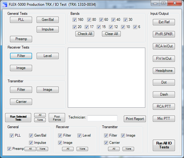
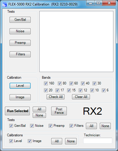
CALIBRATION OF THE RX2
<SHIFT><CNTL>R : RX2 Calibration menu
!!!!!!!!!!!!WARNING!!!!!!!!!!!!!!!
DO NOT touch anything on this page unless you are willing to brick your radio if you mess up.
Calibrations will not work correctly unless you are at Factory Defaults.
(Clicking on "Run Selected" with RX2 & Antenna RX1-tap connected to a Dummy load will go through a series of TX and RX adjustments)
Other Hidden Menus
<SHIFT><CNTL> I: Voltage & Temp
<SHIFT><CNTL>S: Preselector
<SHIFT><CNTL>C: EEPROM Calibration restore, save, reset
<SHIFT><CNTL>V: VU Calibration
Flexwire I2C.
ZZFY CAT command can be used to send a I2C command (address and 2 bytes of data). This can be used to program any I2C IC
The HERO preselector menu button sends a address = 0x40 with 2 bytes of data representing the Band and Ant selected from that HERO panel.
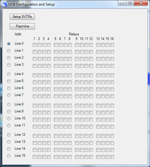
CNTL + ALT + U sends address 0x4c + data to trigger external relays. But its for use only with the XVTR screen
DEBUG SCREEN
<SHIFT><CNTL>D: Debug, check& set drive & final bias Amps,
carrier Null, scanner
!!!!!!!!!!!!WARNING!!!!!!!!!!!!!!!
DO NOT touch anything on this page unless you are willing to brick your radio if you mess up.
(Clicking on the Q2,Q3,Q4,Q1 values will adjust the Drive levels and change the Transmit Idle Amp levels)
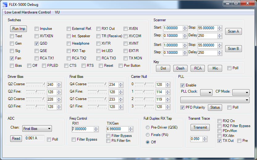
Test=?
Gen=?
Sig=?
Fan= PA fan on/off
Bias= I believe these values are set when you run the PA Bias calibration stated up above. This section allows you to override them.
Carrier Null:
I believe these values are set when you run the TRX calibration state up above. This section allows youto override them.
Impulse= I believe these values are set when you run the TRX calibration state up above. This section allows youto override them.
XVTXEN=?
QSD = Quadrature Sampling Detector (receiver on/off)
QSE =
Quadrature Sampling Encoder (on/off)
RCA TX1,2,3, = key TX1 ,2,3
Off=?
FPLED=?
CTS=?
External Ref= 10 mhz GPS ref ?
Int Speaker=there is none on the 5000a, although I see a provision on the PCB for an audio speaker amp.
Headphone =
Update your Radio's TURF Region:
PowerSDR 2.7.2 GPL & 2.8.0 source code
Current source code can be found at: https://github.com/ke9ns/PowerSDR_ke9ns_v2.8.0/
This mod project was started 1/1/2016 by me, Darrin KE9NS and is based upon
the GPL Open Source PowerSDR 2.7.2 code provided by Flex Radio Systems, Inc.
With generous help provided by Flex Radio Systems, Inc. (Thank You!)
This Source code includes 5 project under the PowerSDR umbrella: DttSP written in C, PowerMate written in C++, PowerSDR written in C#, Inno Setup Compiler (to create the Full Installer), and Advanced Installer 14.5 (to create the incremental installer)
DttSP and PowerSDR code was provided by Flex Radio Systems, Inc.
PowerMate code was provided by Griffin, Clev R. Munke, and me Darrin ke9ns
PowerSDR modifications beyond 2.7.2 are provided by: me Darrin ke9ns, and dh1tw for the DJConsole code
SWL.csv file from eibispace.de (thank you)
SWL2.csv file of my own with additional short wave stations. It is automatically added to the SWL.csv list
dxloc.txt file initially from HRD (thank you), modified by me Darrin ke9ns
EN.dat file updated by the FCC at: https://wireless.fcc.gov/uls/data/complete/l_amat.zip Note: I_amat.zip is a large file and I only use the EN.dat file inside.
FCCDATA.dat file generated by PowerSDR itself from the EN.dat file. This file is to determine the US State.
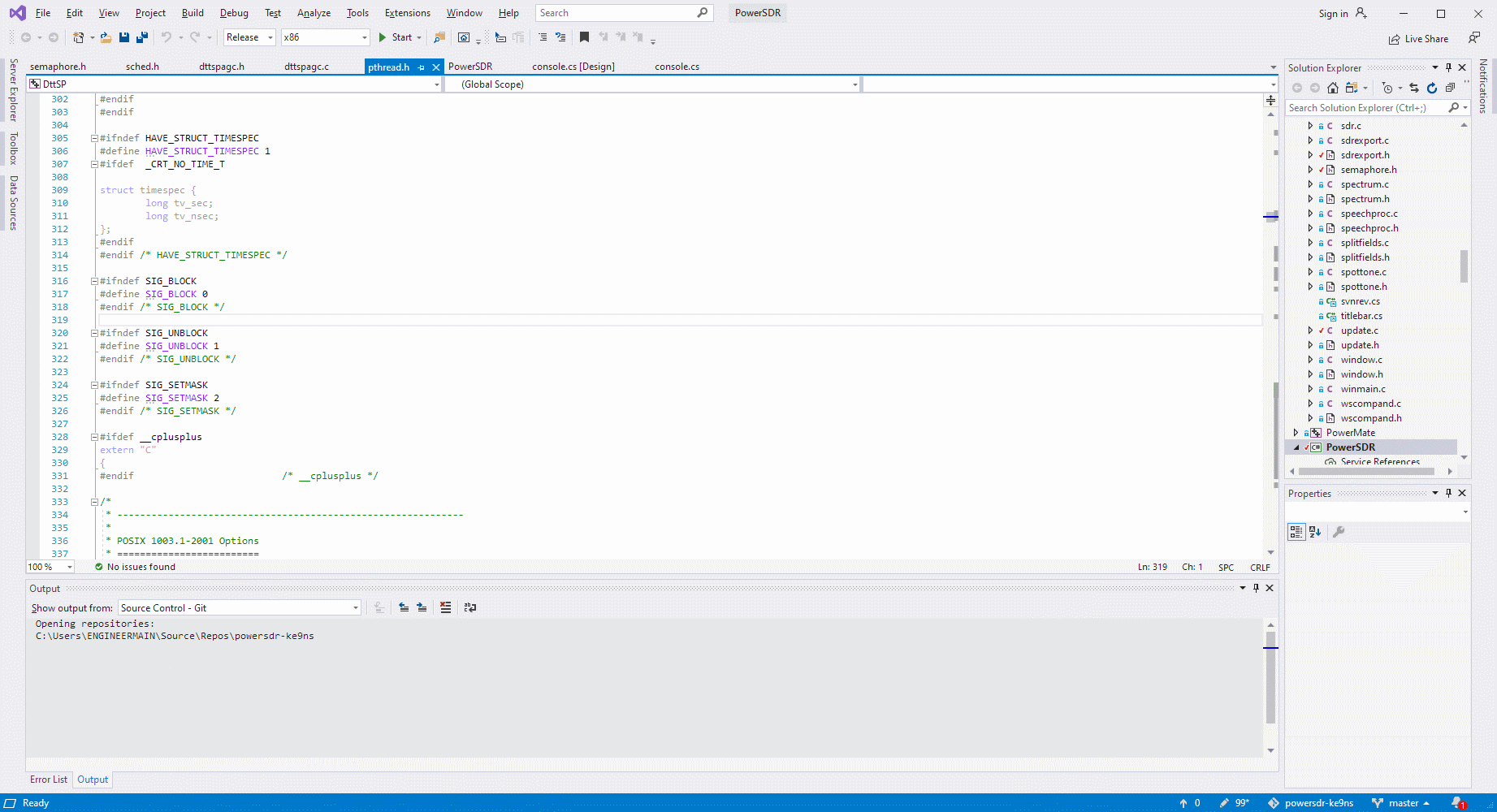
Currently compiling under Visual Studio 2022 (VS2022) and NET 4.5.2
After you download and install VS2022, you must then download and install any VS2022 updates.
When you load the PowerSDR project in for the first time, VS2022 will attempt configure it with NET 8.
But you then must open PowerSDR "Properties" and select or install .NET 4.5.2 before attempting to compile.
Newer versions of .NET will compile but will not run properly on computers configured to use a comma delimiter.
You can run the build from within VS or directly from the VS project release or debug folders.
PowerSDR.exe and PoweSDR.config.exe are the only files needed in the PowerSDR build.
DttSP.dll is the only file needed in the DttSP build.
PowerMate.dll is the only file needed in the PowerMate build.
ALSO: vcruntime140.dll needs to be copied onto the target computer (PSDR program files folder, or download the free C++ VC2015 runtime installer)
Also, I have 2 installers: 1) a Full installer using "INNO Setup", and 2) An Incremental installer using" Advanced Installer"
Do a full rebuild the first time you open the project in VS, before doing anything else.
Things I needed to do before the PowerSDR would actually run:
1) Copy the project into the VS project folder. Make sure the Bin and Source folders are both directly 1 level down
from the PowerSDR_v2.8.0 project folder itself, otherwise the paths wont match up to the original project solution information, and it wont compile
2) Copy over the pal.dll from the Standard Flex PowerSDR program files (x86) folder, into the VS release & debug folders,
otherwise the PowerSDR messes up and will ask for a firmware update.
3) Copy over the TNF.dll file from the Standard Flex PowerSDR program files (x86) folder, into the VS release & debug folders.
4) Go into the VS PowerSDR "references" -> Browse, and add the TNF.DLL to the list. Navigate to the Relase folder you placed it in.
5) Go into the VS PowerSDR "properties" and remove the NO_TNF reference from the "Build" compile list (you need to do this 2 times: Debug and Release)
6) Copy over the ATU.dll file from the Standard Flex PowerSDR program files (x86) folder, into the VS release & debug folders.
7) Go into the VS PowerSDR "references" -> Browse, and add the ATU.DLL to the list. Navigate to the Relase folder you placed it in.
8) Go into the VS PowerSDR "properties" and remove the NO_NEW_ATU reference from the "Build" compile list (you need to do this 2 times: Debug and Release)
9) Rebuild the solution: Release or Debug. Now you will have a full working PowerSDR version that you can start your own modding
10) Remember PowerSDR C# is based on 96dpi resolution and Photoshop default is 72dpi, so images created on Photoshop will be too big unless you set the DPI to 96 and then select your canvas size in pixels.
The "//ke9ns add" call sign comment to indicate code I added
The "//ke9ns mod" call sign comment to indicate modifications to original 2.7.2 source code
PowerSDR open source code provided by Flex Radio Systems, Inc. is covered under GNU GPL Ver 2
This requires anyone who distributes this code to note its authors.
If you wish to add to this PowerSDR ke9ns project, as opposed to starting with the Flex 2.7.2 version, please contact me Darrin Kohn ke9ns@ke9ns.com
73
Darrin ke9ns.com
NOTE: v2.8.0 requires vcruntime140.dll. The Installer copies this file over, but If PowerSDR still fails to run,
you can download the Microsoft installer: https://www.microsoft.com/en-us/download/details.aspx?id=48145
______________________________________________________
PowerSDR KE9NS v2.8 Feature explanation
"SWL List" Key word search:
ALE: Automatic Link Establishment (Decode using PC-ALE)
WWV, Time: Time signals (Both Voice and digital. Decode using WWV HF checkbox and Time Sync button)
VOLMET: Weather information for Aircraft in Flight (Voice)
HFDL: HF Data Link for Aircraft location (Decode using PC-HFDL)
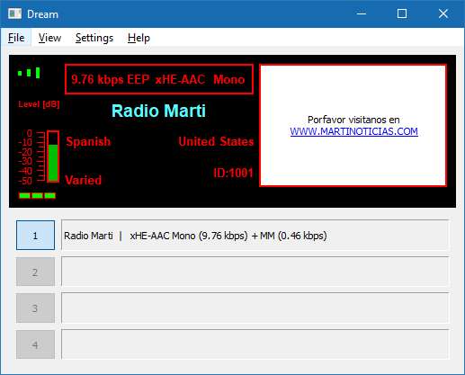
Digital: DRM Radio stations (Decode using DREAM decoder)
Stanag: UN / Military digital (Decode using Sigmira or Sorcerer)
Fax: Weather charts (Decode using Fldigi)
DSC: Digital Selective Calling for Marine ships reporting position or emergency (Decode using Yadd)
Navy: Navel trafic (Voice)
Navtex: Digital Marine Weather (Decode using Navtex)
Mobile: Mobile Marine Radio
Maritime: voice Maritime traffic
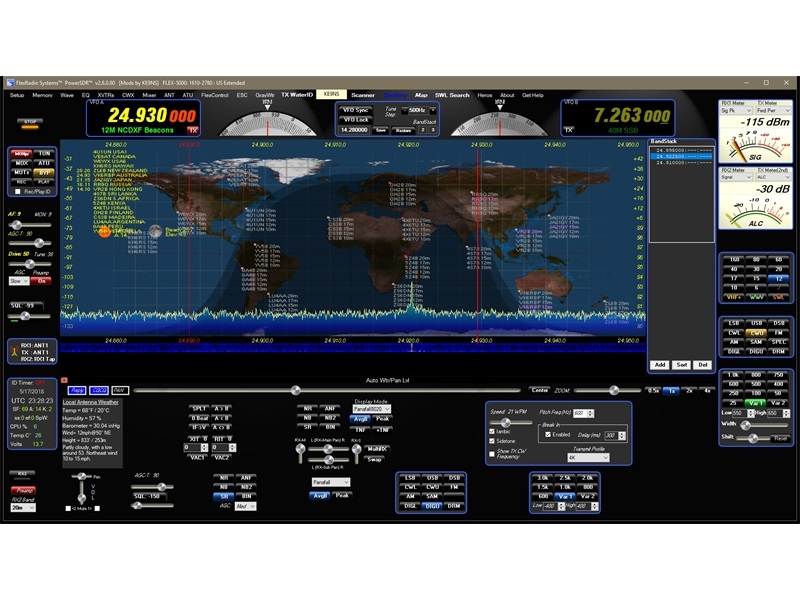
Beacon: NCDXF/IARU Beacons (see ncdxf.org for details).
_______________________________________________________________________
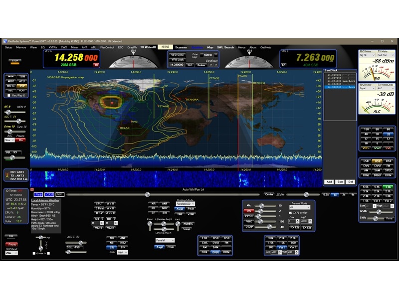
PowerSDR KE9NS "Voacap" Propagation Mapping:
Example
ss:0 ef:15 SpW:
(ss) is the official optical sunspot number from SIDC. The higher the better.
(ef) is the effective sunspot number, which is based on soundings of the ionosphere,
but only for the mid latitudes of the earth.
The effective SunSpot number is more accurate than the optical. The higher the better.
The only number you want low is the (K) (high K means signals will likely be scattered rather than reflected)
VOACAP propagation uses the (ef), so its more accurate, but it doesn't take high (K) values or (SpW) geo storms into account.
VOACAP propagation assumes you have a rotatable dipole or 3 element beam at 35' (if you select it)
Dots: The Dots show signal strengths computed for the exact locations over the map. Areas on the map with small or no Dots have the weakest signals.
Large Dots have stronger signals.
Blue is the strongest signal, then Green, then Orange, then Yellow, then Gray
Contours: Contour lines are derived by a formula from the dots, but can sometimes be difficult to see coverage gaps on the map.
Blue is the strongest, then Green, then Orange, then Yellow, then Gray.
The problem with contours is it is hard to determine the Gaps in coverage. You may see a Blue contour line, but if you change over to the Dots map, you will see no signal strength adjacent to the Blue area of the map. (i.e. a Gap)
Reasons you may hear stations when the Propagation map shows no conditions:
Some Ham Radio stations have large Antenna arrays and may show up on an empty part of the Propagation map, due in part to their very large Effective Radiated Power (ERP) when compared to a wire dipole.
Or,
at 27mhz or above, Tropospheric Ducting Propagation maps
(see https://www.dxinfocentre.com/tropo.html)
and/or Sporadic E propagation (Estimated Sporadic E layer (DXMAPS.com))
You may not hear stations that are in a Blue or Green area of the map, due to Antenna directionality, takeoff angles, Geo Storms,or high K readings, or they may be in Gaps found in the propagation area
__________________________________________________________________
DX Cluster Lists:
See https://www.dxcluster.info/telnet/index.php for a list of DX clusters that you can add to the list in PowerSDR Spotter window.
__________________________________________________________________
PowerSDR S-Meter dBm vs Panadapter dBm:
Why is the S-Meter reading showing a signal level different from the signal I see in my Panadapter bandpass?
This is because the S-Meter reading is the Sum of all the DSP FFT bins taken within the bandpass filter. And they are related by 20log(bandwidth inside receiver filter / bin size of FFT) as per N5AC.
If you were to close down your bandpass to around 10hz, the signal within that bandpass and the S-Meter should now be the same dBm (if both meters are running at the same refresh rate and you take into account any averaging being done).
So,
as you open up the bandpass filter, the S-Meter will rise as you add (sum) more bins.
This is as it should be and works the way a traditional S-Meter works.
Note: the S meter scale on the right side of the Padapter is approx because it only follows the dBm markings found across on the left side of the Panadapter. So in order to see a correct scale on the right side matched to the left side, you would need to set your setup->Display->Spectrum Grid->Max = -19, Min = -135, Step = 6 (S signals are 6 dBm apart). But if you use the Auto Pan Lvl button, the Max value will change automatically.
__________________________________________________________________
PowerSDR ke9ns keyboard and Mouse shortcuts:
with all the Hidden menus
keyboard shortcut pdf
How to configure you Flex when using an AMPLIFIER with its own external Tuner and still use RX2. With an 2x6 antenna switch
If you happen to use an Amplifier (like most) with your flex and more than 1 antenna, it is not possible to use the built in antenna switch.
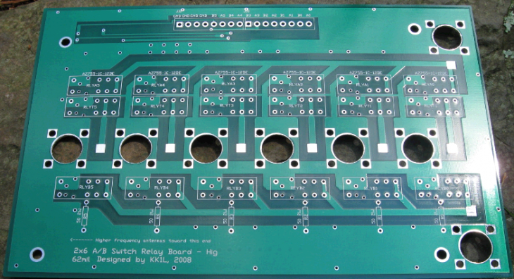
The best way around an external Amplifier but multiple receivers issue is a SO2R antenna switch (as shown below)
See https://home.comcast.net/~kk1l/kk1l_2x6switch/ or https://ac0c.com/main/page_so2r_kk1l_2x6_ant_switch.html
I added a homemade aluminum box and a remote switch head (just 6 3pos SPDT toggle switches)
This allows me to select any of 6 antennas for any of 2 radios. This way RX1/TX on the Flex always goes through the Amplifier no matter which antenna I choose, and RX2 never goes through the amplifier no matter which antenna I choose.
My setup: Ant #1: G5RV, ANT #2: Cushcraft R7, ANT #3: Mosley TA-33 Yagi, ANT#4: Cantenna Dummy Load
Below is a short youtube iphone video I took showing SO2R (Single Operator 2 Radios or 2 Receivers) operation.
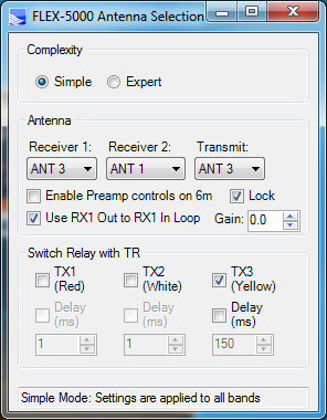
Below: RX1 needs to be on ANT3 because RX2 cannot. Plus you can also switch RX2 over to RX1 tap (to share the same antenna). Note the Use RX1 Out to RX1 in Loop is for the External AM broadcast filter.
(FDX) Full Duplex Operation or (SO2R) Single operator with 2 receivers
Because RX1 and RX2 are seperate and independant modules inside the Flex 5000, its easy to do cross-band FDX or SO2R.
Below is a short youtube iphone video I took showing Full Duplex Operation. Do NOT try Full Duplex on the same band. Be careful to test out your setup first at low power to make sure you have good isolation when transmitting. When you are sure that your 2nd receiver is not picking up your Transmitter, then start raising the power.
I have tested this out, and its possible to receive on 20m using RX2 (VFOb) using a Yagi tri-bander, while transmitting 100 watts on 80m using VFOa and a G5RV ant. Both antennas are around 100' apart. I found no change in the noise floor when transmitting. I believe this would work on any band combination as long as you use 2 different antennas and they are spaced far enough apart.
I was also able to receive on 40m (using a R7 vertical) while transmitting on 80m
using the G5RV. Both antennas are around 100' apart. But you need to make sure not to overload the 2nd RX if you run any power.
You dont need the SO2R switch (described above) to make this work. The SO2R switch is only needed when you have more than 2 antennas and/or you have an amplifier.
You simply to go the Setup Menu and set the proper switches.
Connect 2 antennas to the Flex and set the antenna swtich menu up properly for your configuration.
!!! Receiver2 must have its own antenna for FDX !!!

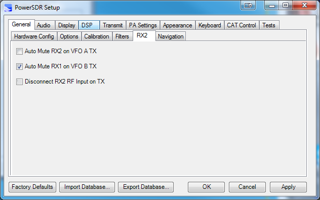
Go to Settings->General->RX2:
1)
Uncheck "Auto Mute RX2 on VFOA on TX"
2) Uncheck "Disconnect RX2 RF Input on TX"
3) if you plan on Transmitting on VFOb (SO2R operation), then Uncheck "Auto Mute RX1 on VFO B TX" as well
!!!! Make absolutely sure to put back the switches on this menu when your done!!!
4) Now select one band for VFOa and a different band for VFOb
5) Test it out at low power to make sure you dont overload RX2 (or RX1 if transmitting on VFOb for SO2R operation)
6) You may see the noise floor go up if your TX and RX frequencies are close
I have not tried FDX on the same band (Flex says its possible on the 6000 series)
I am not sure how to configure logging software for SO2R (Flex has a procedure for the 6700)
!!! Make absolutely sure to put back the switches on this menu when your done !!!
Listen, or Record and playback your Transmit Audio
There are a couple of ways to hear yourself thru the Receiver directly, for TX Audio checks:
(Just remember the PowerSDR [REC] / [PLAY] records only RX1)
First, The [MON] button will let you listen to yourself, but with a slight digital delay, so its not really usable.
---------------------------------------------------------------------------------------------------------------------------------------------------------------
1) You can use [WAVE] and [RECORD] your audio (POST audio as it is applied to the PA). [MON] does NOT need to be on. I would keep it off to prevent any echos in the recording.
a) Turn the Power out put to 0, and PTT the Flex.
b)
Hit the [RECORD] button in the [WAVE] menu, and talk (make your recording)
c) Hit the [RECORD] button again to end the recording.
d)
The %userprofile%\Music\PowerSDR\ folder contains all the recordings made using the [WAVE] button.
e) You can then take the file you just created and rename it SDRQuickAudio.wav and save it in the %userprofile%\AppData\Roaming\FlexRadio Systems\PowerSDR v2.7.2 folder (which is where the [REC] / [PLAY] buttons work.
f) Now you can PTT the Flex and hit the [PLAY] button to play back your clip.
note: if you hit the [REC] button, your audio clip will be overwritten.
---------------------------------------------------------------------------------------------------------------------------------------------------------------
2) or You can Leave the Receiver RX1 or RX2 on while you transmit
(explained below)
WARNING: DO NOT overload RX2.
Hear Yourself using RX2 (the 2nd receiver):
Go to Settings->General->RX2:
1)
Uncheck Auto Mute RX2 on VFOA on TX
2) DONT Uncheck Disconnect RX2 RF input on TX
(this will allow you to not worry about the DRIVE level on transmit).
3) Your TX ant should be a Dummy Load.
4) Plug in Headset to the Flex because the RX2 will not shut off when you transmit
I dont believe you can use the built in recorder to record RX2?
I use VAC2 to send the audio to the PC and record it using SpectraPlus

8bit address (not 7 bit) list for FlexWire output:
0x40 HERO's preselector
0x42 Band selector output for PCA9534 (1st) 8bit I2c chip (2200m=1 - 20m=128)
0x44 Band selector output for PCA9534 (2nd) 8bit I2C chip (17m-6m)
0x46 Band selector output for MCP23017 16bit I2c chip (2200m-6m)
0x48 Not used
0x4A LDMOS Amp Filter board selector PCA9534 (w6pql current design)
0x4E LDMOS Amp Filter board selector PCA9534 (w6qpl old design)
0x4C UCB (Universal Control board) Relay selector. PCA9555D (part of the Xvtr panel)
Flexwire I/O connector is a DB-9 female serial type connector wtih pin 3 blocked so you dont try to plug a serial bus into it.
DB-9 connector view from back of radio:
(
6-7-8-9 )
(1-2-3-4-5)
1: Ground
2: Line In
3: Blocked
4:/INT1
5: Ground
6: IIC CLOCK (SCL)
7: IIC DATA (SDA)
8: +13.8vdc out (1A max)
9: Line Out
IIC bus uses pin 5,6,7 low speed (100khz) bi-directional synchronous data bus. IIC bus allows multiple devices on the same bus where each device has an address 8bits long.
Important NOTE: example: 8bit address 0x46 = 0,1,0,0, A2,A1,A0, 0 = (01000110)
(bit0 determines Read/Write but its still part of the address byte)
---------------------------------------------------------------------------------------------------------------------------------------------------------------
KE9NS added I2C (IIC):
Setup->General->User Interface->I2C Band Output checkbox
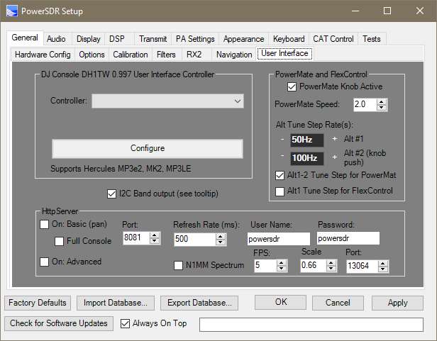
Upon band change, PowerSDR will send 2 IIC command strings:
(For PCS9534 I2C port replacement chip)
1) 8bit Address 0x42 Register 0x01 Value = <DATAA>
2) 8bit Address 0x42, Register 0x03, Value = 0x00
<DATAA> (below)
2200m = 1, 630m = 2, 160m = 4, 80m = 8, 60m = 16, 40m = 32, 30m =64, 20m = 128
-------------------------------------------------------------------------
(For PCA9534 I2C port replacement chip)
1) 8bit Address 0x44 Register 0x01 Value = <DATAB>
2) 8bit Address 0x44, Register 0x03, Value = 0x00 (all output)
<DATAB> (below)
17m =1, 15m = 2, 12m = 4, 10m = 8, 6m = 16, reserved = 32, reserved = 64, reserved = 128
------------------------------------------------------------------------
(For MPC23017 I2C 16bit port replacement chip):
8bit address 0x46, register 0 & 1 to 0 (all output on PortA & B)
8bit address 0x46, register 0x12<DATAA>
8bit address 0x46, register 0x13 <DATAB>
--------------------------------------------------------------------------------------------------------------------------------------------------------------
UCB (FlexWire Button) using PCA9555D IC
Open on XVTR page, you will find a FlexWire button OR
<CNTL> + <ALT> + U: "UCB" Universal Control Board Configuration page
Note: When FlexWire Button is "Yellow" then the IIC output is active
See page: k3tuf.com/FW.html , for info on FlexWire and UCB
This is used in conjunction with the XVTRs menu and the VHF+ button on the main PowerSDR screen
On the XVTR menu enable a item and give it a UCB Line Number. This corresponds to the above screen. You then select which relays activate for each UCB line number. The VHF+ button on the main screen is how you access this new band.
UCB transmits via IIC bus the following 4 sets of 3 bytes (PCA9555D):
0x4c, 0x06, 0x00
0x4c, 0x07,0x00
0x4c, 0x02, (low 8bits value of line#)
0x4c, 0x03, (high 8 bits value of
current line#)
ZZFY CAT command can be used to send a I2C command (address and 2 bytes of data). This can be used to program any I2C IC
---------------------------------------------------------------
The HERO preselector menu button sends a address = 0x40 with 2 bytes of data representing the Band and Ant selected from that HERO panel.
Current HERO Preselectors have a USB connection to CAT and no longer need the I2C output.
---------------------------------------------------------------------------------------------------------------------
KE9NS Amplifier control using IIC
Activate the feature from:
Setup->General->Options->Use IIC FlexWire for External AMP Control,
and Setup->General->Options->IIC FlexWire AMP ON/OFF checkboxes.
Upon Band Changes the following 6 bytes of data are transmitted via IIC bus
Older W6PQL LDMOS RF Filter Design (address 0x4E)
0x4E, 0x01, <DATA>
0x4E, 0x03, 0x00
Current W6PQL LDMOS RF Filter Design (address 0x4A)
0x4A, 0x01, <DATA>
0x4A, 0x03, 0x00
<DATA>:
1 = Select bands: L/MW, 160m, 120m (no relay needed with W6PQL design filter board)
2 = Select bands: 90m, 80m, 61m, 60m, 49m
4 = Select bands: 41m, 40m, 31m ,30m
8 = Select bands: 25m, 22m, 20m, 17m, 16m, 15m, 14m (Address 0x4E only)
16 = Select bands: 13m, 12m, 11m, 10m (Address 0x4E only)
and
8 = Select bands: 25m, 22m, 20m, 17m, 16m(Address 0x4A only)
16 = Select bands: 15m, 14m 13m, 12m, 11m, 10m (Address 0x4A only)
32 = Select bands: 6m
64 = Remote ON/OFF (used N.C. contact... 64 relay on = remote control)
128 = Selected bands: VHF/UHF (bit7 is turned OFF)
<DATA> bit6 (64) is SET only if IIC AMP ON/OFF checkbox is set and on an HF/6m band
See my SS AMP page for controller board circuit
Digital Decoders (with further detail in the next section)
All decoders tested with
the Flex unless stated otherwise
Audio stream via VAC (Virtual Audio Cable) and Firewire connection (no audio cables required)
USING VAC: Because of Sample Rate (SR) up & down conversion between the Radio itself and VAC1, its best if you use 48khz SR for VAC1 & 2. This is because its a perfect multiple of 192 and 96khz SR.
You must also set the SR for your Virtual audio cables to 2 channel 16bit 48khz (for both Playback and Recording VAC cables (see Windows->Control Panel->Sound).
Failure to do so, will most likely result in buffer lag, which will cause Digital mode PC programs (like WSJT-X, FLDIGI) to not work correctly. If you do notice a lag in VAC audio, check all your Sample Rates to make sure they are ALL set to 2 channel 16bit 48khz.
There are many digital signals present throught the HF band, however most outside of the Ham bands use special digital modes and/or are Encrypted
See website for signal indent guide:
https://www.sigidwiki.com/wiki/Signal_Identification_Guide
------------------------------------------------------------------------------------------------------------------------------------------------
Satellite Work:
(GPREDICT satellite prediction and pointing):
Flex-5000 (with the VU5K module) or external transverters for 2m/70cm:
1) Gpredict.exe
2) Hamlib-w6 (rigctld.exe) (example: rigctld.exe -vv -m 2048 -r COM12 -s 57600). Make sure rigctld.exe is running, then minimize its window.
3) In Gpredict, Edit->preferences->Interfaces->Add new->Host=Localhost, Port=4532, Radio Type=Duplex TRX, PTT Status=None, VFO Up/Down= B/A, LO down=0, LO up=0
4) In Gpredict, Edit->preferences->Ground Stations. Put your location in. TLE Update=Daily
5) In Gpredict, click on the small down arrow in the upper right corner, select configure. Now create a Group (i.e. SSB or FM) and add satellites for that group.
6) In PowerSDR, turn on RX2, Click on the VFOB TX button, then Right Click on it again, to lock it into TX
7) In Gpredict, Click on the small down arrow (upper right corner), then "Radio Control" then select the satellite and mode you want to use. Then the Track and Engage buttons
8)
In PowerSDR, for SSB satellites (once Gpredict is up and running and Engaged) you will need to then turn on RIT and set to -1300 for RS-44. All SSB linear satellite differ based on the spin and angle.
For commuincated APRS with the Space Station digital mode
UISS (by ON6MU)
SoundModem (by UZ7HO)
------------------------------------------------------------------------------------------------------------------------------------------------
PinPoint APRS:
Make sure the Flex Radio is in 5FMD (Data FM with 5khz dev)
Then select Tools->Connect TNC (with SoundModem running, and VAC1 on the Flex connect to SoundModem), you can now transmit (make sure VOX is on and set for Fast trip, long hold). Now you can select Tools for Send Position, Send Message, Send email, Send Bulletin, Send message via winlink, etc.
Go to GPS screen to select your Lat/Long position. Then you can also go to aprs.fi to check as well:
------------------------------------------------------------------------------------------------------------------------------------------------
Amateur Email (Winlink Express)
USAGE: Email, File transfer
ENCODER/DECODER: Winlink Express installer: https://downloads.winlink.org/User%20Programs/
TNC software: VARA HF or FM modem. https://rosmodem.wordpress.com/
MODE: USB 2.7khz wide
FREQ: CW portion of ham bands
SOUND: Click to download audio file to hear what it sounds like
Email: RMS (Radio Message Server) Express is a free program for sending/receiving digital messages (ie. email). Download and install "Winlink" and "VARA HF" and/or "VARA FM" (for VHF winlink and APRS) as the modem.
Winlink demo video:
Winlink (left) and VARA modem (right)
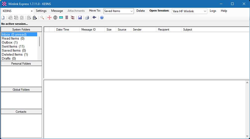
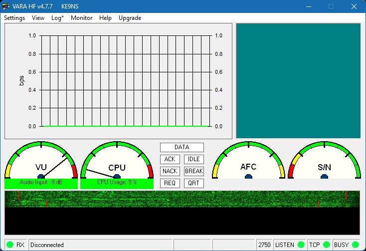
Winlink setup(left) and Winlink Vara setup (right)
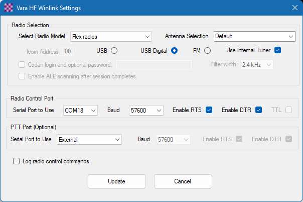
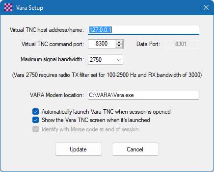
PowerSDR CAT and VAC setup(WSJT-X is the same I use for Winlink)
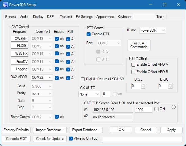
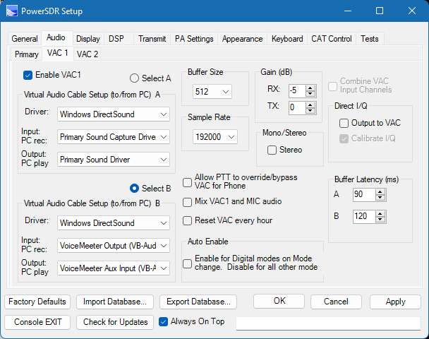
Windows PC (Sound) settings to match the Sample Rate of PowerSDR)
Winlink to PowerSDR (sound playback panel) (left) and PowerSDR to Winlink (sound recording panel) (right)
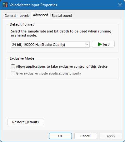
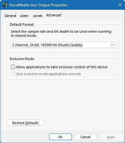
Make sure to Activate VOX for ultrafast RX/TX transfer (left) and Vara Sound Setup (right):
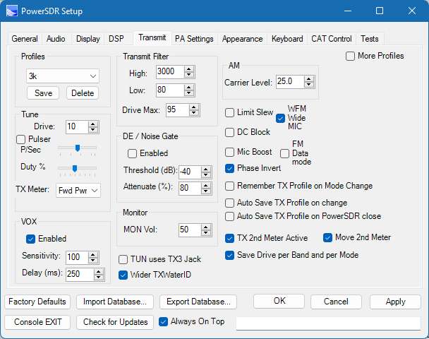
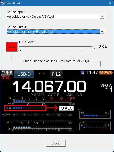
Winlink using VARA HF modem (channel select) then Connect (make sure to use VOX):
PowerSDR Winlink transmit (Vox Enabled):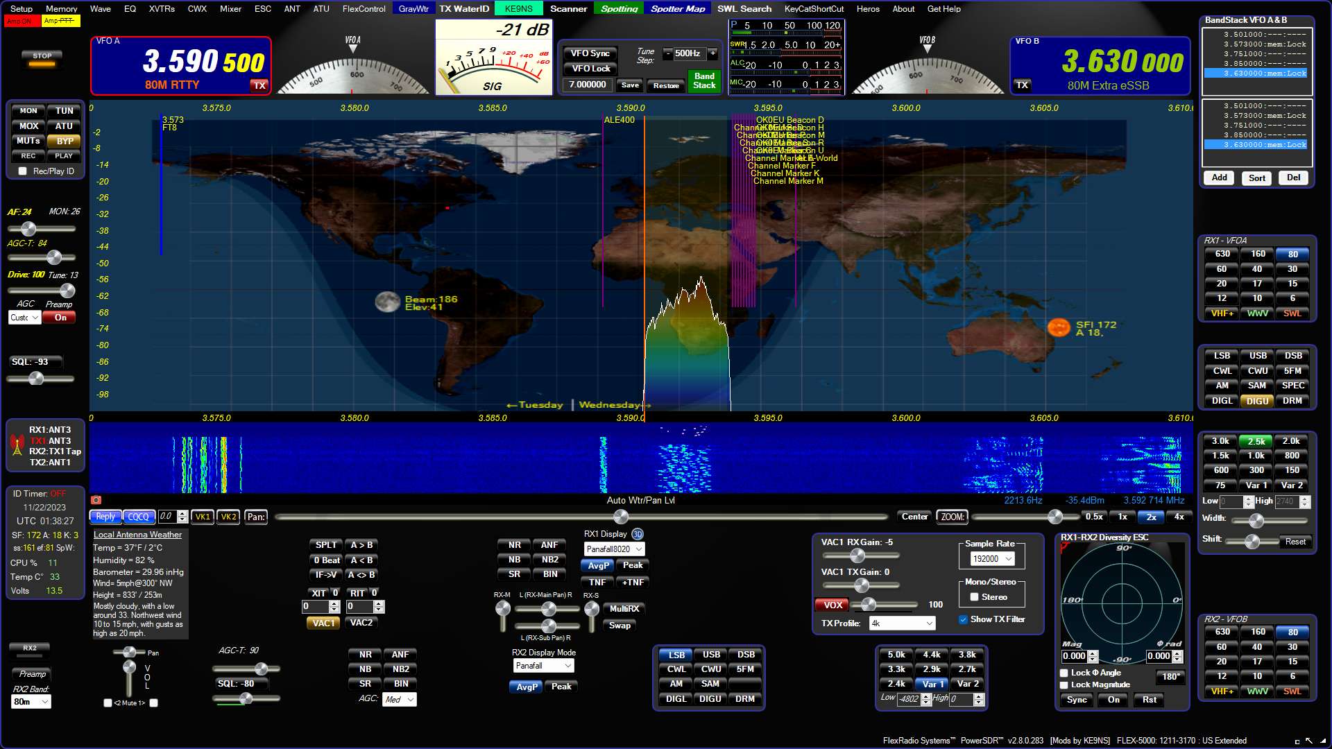
------------------------------------------------------------------------------------------------------------------------------------------------
Amateur FT8 (using wsjt-x)
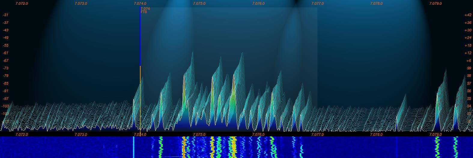
NOTE: FT8 has a rather large penalty on your CPU in a crowded band (like 80m and 40m) trying to decode 20 or so signals simultaneously. The more signals to decode, the higher CPU and HDD usage. My old 4 core cpu maxed out at 100% decoding on 40m and running PowerSDR at the same time. I decided to upgrade my desktop motherboard to a 6 core (2 thread / core) and 16gb of DDR4. Now FT8 doesnt cause any troubles.
USAGE: Weak Signal or Poor band condition, very short QSO, QSL Communications. (good for collecting mixed and digital awards and checking antenna performance). After you make a few contacts go to: https://pskreporter.info/pskmap.html and type in your callsign to visually see (on a world map) where your signal is getting out).
ENCODER/DECODER: WSJT-X (with JTAlert-X for checking QSL information and interfacing with your Logging software)
https://physics.princeton.edu/pulsar/k1jt/wsjtx.html and https://hamapps.com/
FT8 decode signals down -26dBm below the noise in 15sec sequences (up to 13 characters per sequence) with a typical 4 sequences
Use the TIME sync function in PowerSDR to sync your PC clock (must launch PowerSDR in ADMIN mode).
Use vsgMgr, DDUtil, and Virtual Audio Cable to link PowerSDR to wsjt-x
In wsjt-x radio setup use TS-2000 for now and set PowerSDR CAT to allow kenwood commands.
When you see a RED or VIOLET CQ signal appear in the Left "Band Activity" panel, click on it
(Here is the awkward part:As soon as the CQ appears you only have 1-2 seconds to respond, otherwise you must wait for the next 15 second TX interval).
Your Transmit appears in YELLOW on the right "RX Frequency" panel.
If the CQing station decodes your call sign, you will see them calling you as a RED decoded line the the Right "RX Frequency" Panel
wsjt-x will automatically step through the sequences (after you start by clicking on the CQ station) for short QSL exchange (15 seconds per line):
:
JTAlert-X scans your main logbook and the wsjt-x logbook and automatically adds your contacts to your main logbook.
And, it keeps track of what you need (Zones, States, Countries, Grids, etc.) and alerts you immediately after every "Decode"
MODE: Band Mode (USB on all bands). FT8 signals are 100hz wide found in a 2.5khz bandpass area
FREQ: 1.840, 3.573, 7.074, 5.357ch3, 10.136, 14.074, 18.100, 21.074, 24.915, 28.074, 50.313 Mhz
SOUND: Click to download audio file to hear what it sounds like
(top left: signal as it appears in PowerSDR panafall) (top right: wsjt-x encoder/decoder)
(bot left: wsjt-x waterfall allows you to manually select a transmit frequency within the bandpass)(bot right: JTAlert-x reads the decodes from wsjt-x)
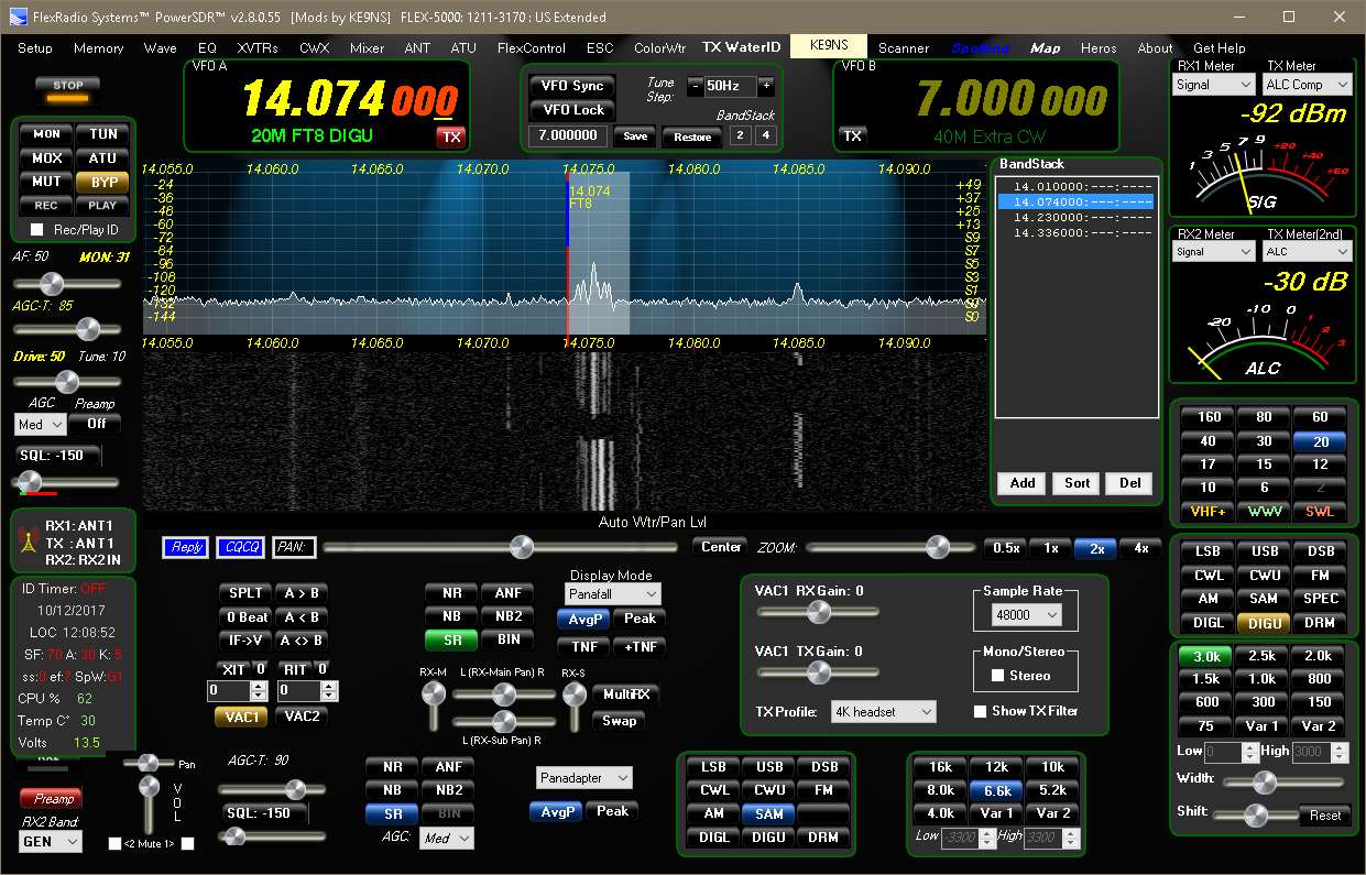
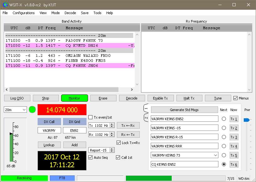


WSJT-X SPLIT operation:
Example: For FT8 with Japan, VFOA = 1908, VFOB=1840, TX=VFOB, Click VFO Lock button until it reads "VFO A/B Loc"
Then setup WSJT-X, TS-2000, SPLIT= NONE
WSJT-X multi-instance operation:
(For those Flex-5000 and 2nd receiver RX2 option)
This is the normal WSJT-X Desktop ICON Property: C:\WSJT\wsjtx\bin\wsjtx.exe
To create the 2nd WSJT-X icon (that can run simultaneously with your current WSJT-X Icon):
1)
Open file location: C:\WSJT\wsjtx\bin
2) Right click on the WSJT-X
and send to ->Create Desktop shortcut
3) find the next WSJT-X shortcut icon on your desktop, Right click to rename WSJT-X2
4)Right click and select Properties and change
C:\WSJT\wsjtx\bin\wsjtx.exe to say:
C:\WSJT\wsjtx\bin\wsjtx.exe --rig-name=Flex5000RX2
5) run this WSJT-X and WSJT-X2 and run setup to config as below (as SO2R):
Left is VFOA, Right is VFOB (NOTE: Use JTAlert to automatically send QSO's to your logging program. JTAlert will automatically handle the 2 instances as long as you setup like you see in the next 4 screen shots)
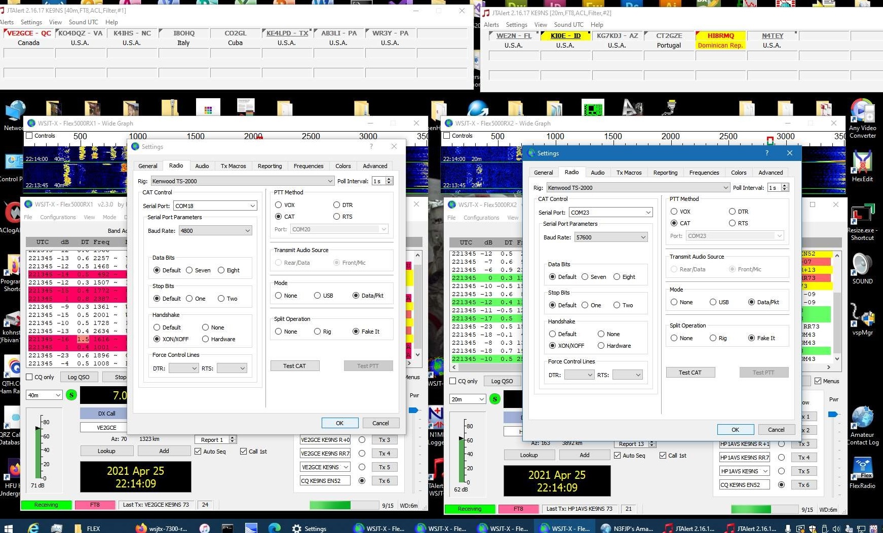
Keep the Baud Rate on both at 57600. the WSJT-X2 (on right) uses the COM23 because its paired iwth COM22 in PowerSDR and that is the RX2 VFOB CAT COM link.
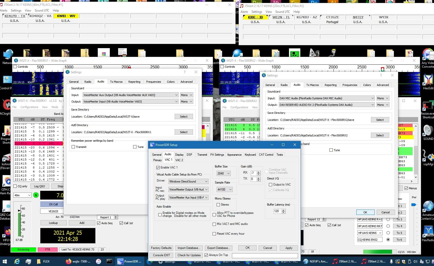
I use VoiceMeeter Banana as 1 set of VAC cables (Left side) for the VFOA setup of WSJT-X.
I use DAX drivers (from a SmartSDR install) as the 2nd set of VAC cables (right side) for the VFOB setup of WSJT-X
You can see the VAC1 configuration for VFOA
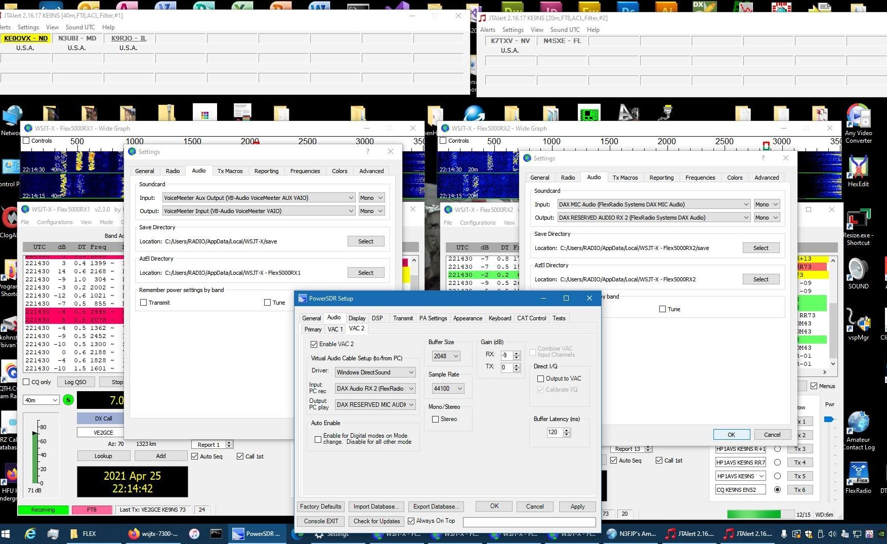
You can see the VAC2 configuration for VFOB
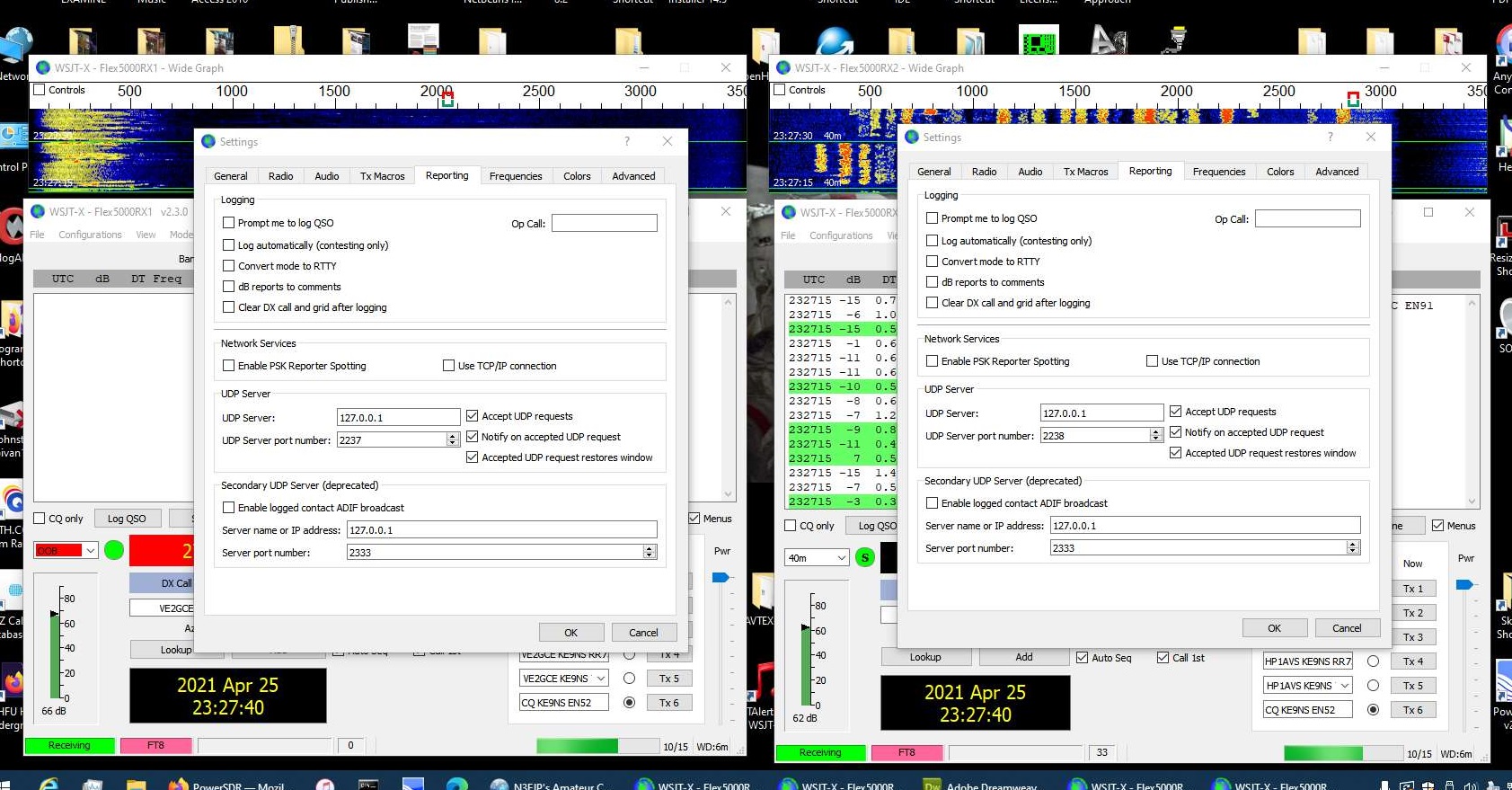
You will need to alter the UDP server of the WSJT-X2 (VFOB) version to allow JTAlert to handle communicaing with 2 instances of WSJT-X
WSJT-X on RX2 VFOB (one instance):
(For those Flex-5000 and 2nd receiver RX2 option)
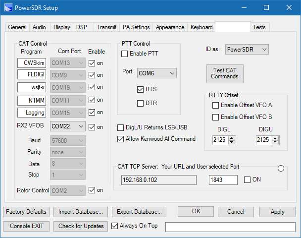
Simply launch the "WSJT-X2" version and this free's up VFOA.
------------------------------------------------------------------------------------------------------------------------------------------------
CWSkimmer
USAGE: CW signal decoder
PowerSDR and CWSkimmer Settings:
1) Assuming you already have VAC1 setup to work with your other digital modes on your PC, just click on the VAC1->Direct I/Q "Output to VAC" checkbox. CWSkimmer appears to only work with I/Q audio.
2) in CWSkimmer->View->Settings->Radio->Softrock-IF SR set to 192khz, Audio IF = 9600 (This assumes a Flex-5000 with a pitch of 600hz). For a Flex-3000 set to your current SR (likely 96khz)
NOTE: For the Flex-1500 you must select 48khz Sample Rate, and Audio IF = 4400hz (This assumes a pitch of 600hz)
3) In CW mode PowerSDR reports the frequency including Pitch, but CW skimmer does not expect that, so you need to add the pitch to the IF frequency (i.e. 9600hz for 3000/5000 or 4400hz for 1500)
4) in CWSKimmer->View->Settings->Audio->set "Signal I/O device" to match your VAC1.
NOTE: For the Flex-1500 you must select Channels->Left/Right=Q / I
5) in CWSKimmer->View->Settings->Cat->Radio 1->PowerSDR (and your CAT settings like you would any other PC Program)
6) CWSkimmer only appears to work with VFOA and when your in CWU mode (not CWL)
7) Use PowerSDR->CWX panel (or your own Key) to transmit
8) Click on the little Radio icon in CWSkimmer (upper left corner) to start it working.
9) Remember to turn off the I/Q checkbox when your done, otherwise you will go crazy trying to figure out why FT8 doesn't work :)
------------------------------------------------------------------------------------------------------------------------------------------------
DREAM.EXE (Digital Audio decoder):
Click here DReaM_v2.2.1_zefie1.1_xHE-AAC_FDK_Win8.1_x86 to Download the latest v2.2.1 (compiled with VS and QT5.12.0 and works with xHE-AAC support).
The new version of DRM allows for lower bitrate requiring lower SNR
You must also install NPCAP (new version of WinPCap) from here: https://nmap.org/npcap/
This compiled version was posted here: https://www.reddit.com/r/RTLSDR/comments/grp6m2/dream_v221_for_windows_with_xheaac_support/
FLDIGI.EXE (multiuse): CW,CONTESTIA,DOMINOEX, HELL, MFSK, MT63, Olivia, PSK, QPSK, PSKR, RTTY, THOR, THROB, WEFAX, NAVTEX-SITOR5, WWV
(Easy to use, TX & RX)
SIGMIRA (multiuse): FSK,PSK31,SITOR-B,CW,HFDL, STANAG 4285, JSM
(Easy to use, works well, TX & RX) (But requires a feature.dat date expiring file, which you can overide if you backdate your PC).
Also, Sigmira will only see signals from the DEFAULT windows recording device. I selected my virtual Line 1 as my output, then set it as default in windows.
MIXW2 (multiuse): CW,BPSK31,QPSK31,FSK31,RTTY, PACKET, PACTOR, AMTOR, MFSK, THROB, MT63, HELL, FAX, SSTV
(Difficult to decode in many modes, TX & RX)
MULTIPSK (multiuse): Decodes just about everything, but very difficult to use, doesnt work very well.
CLOCK (from the creator of MULTIPSK): Decodes all the time signals on HF
EASYPAL (images): DRM digital photos, Waterfall pictures
(Easy to use, great waterfall, TX and RX)
DIGIPAN (Ham Texting): BPSK31,BPSK63, QPSK31, FSK31, PACTOR(RX only)
(Easy to use, multiple conversations at the same time, TX & RX)
ALE (Automatic Link Establishment message system): MIL-STD-188-141B, MIL-STD-188-110A,B
(MARS-ALE difficult to control Flex, PC-ALE OK)
RMS Express (Radio Message Server for email/message system): TELNET, PACKET, PACTOR, ROBUST PR, WINMOR (all as WL2K or P2P)
(Easy to use, RX and TX)
MMSSTV (Slow scan TV): Robot36,72,AVT90,Scottie1,2,DX,Martin1,2,SC2,180
(Easy to use, need good signal, TX & RX)
Download at: https://hamsoft.ca/pages/mmsstv-yoniq.php
WSPR (weak signal contacts): (requires PC clock time synced)
WSJTX (weak signal contacts): JT modes (requires PC clock time synced)
WSJT (Version 10): JT modes + ISCAT modes + FSK441 (ISCAT B and FSK441 modes used on 6m 50.248 50.246)
PC-HFDL: Airplane tracking (easy to use)
SORCERER (multiuse): FSK, STANAG, RTTY, CW,
(somewhat difficult to use)
MSCAN METEO (weather): RTTY, NAVTEX, FAX, Voice
(installed, but not tested)
NAVTEX (weather): (installed but not tested)
MMVARI (multiuse): RTTY, FSK, PSK, GMSK
(installed, but not tested)
FREEDV (Digital Audio): (low quality audio, requires strong signal, TX & RX)
WINDRM (Digital Audio): (installed, but not tested)
FDMDV (Digital Audio): (installed, but not tested)
HAMSCOPE (multiuse): RTTY, PSK,FSK
(installed, but not tested)
WINWARBLER: CW,PSK,RTTY
(installed, but not tested yet)
YaDD: DSC (Digital Selective Calling) for Maritime Mobile & Navtex
Links to Sounds Of Digital HF signals:
https://www.nonstopsystems.com/radio/radio-sounds.html
https://www.astrosurf.com/luxorion/qsl-audiofiles.htm
https://www.bcar.us/DigSig.htm
https://wb8nut.com/digital/
https://www.youtube.com/watch?v=bNZBuxIbWM0
------------------------------------------------------------------------------------------------------------------------------------------------
SDCx64 CW Skimmer
Usage: Decoder for CW, RTTY, BPSK
PowerSDR settings:
NOTE: For RX2 to work properly you must treat RX2 just like VFOA and Let PowerSDR "Setup->CAT Control->RX2 VFOB" reroute to VFOB of your Flex-5000. This is because most Ham PC programs that have a Powersdr or PowersdrRX2 rig control dont work properly.
NOTE: Due to a Glitch in SDC, the SKM CW Skimmer may force PowerSDR to the wrong band when you Start the Skimmer. You will need to go to PowerSDR to put the RX1 and RX2 back on the correct bands if SDC accidently changes them.
NOTE: SDC Uses IQ audio and needs to know the offset HZ of the IQ audio. The Flex-3000/5000 default offset is 9000hz and 3800hz on the Flex-1500. But if you run CW mode with SDC, you also need to include the CW pitch offset (which is 600hz as a default). I dont see a place in SDC to include the CW Pitch offset (like the real CW Skimmer does)
Note: I use TS-2000 CAT as the Radio, since PowerSDR CAT is compatible with TS-2000. Most HAM programs that have PowerSDR rig capability do not properly communicate with PowerSDR using CAT PowerSDR (not sure why).
NOTE: If you wish to use SDC to transmit CW, you will want to make sure PowerSDR is in CW mode and not in DIGI or SSB modes.
Below: CAT setting for SDC:For RX1 just pick a COM port pair (in my example I have COM18-COM19 pair).
For RX2 you need to use the RX2 VFOB (I have it set a COM22-COMM23 pair). Note the 115200 Baud that you will need to put into SDC RigSync setup.
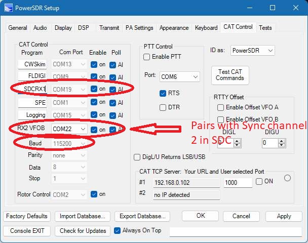
Below: VAC1 setup using free Voicemeeter drivers for RX1
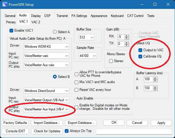
Below: VAC1 setup using free VB-Cable drivers for RX2
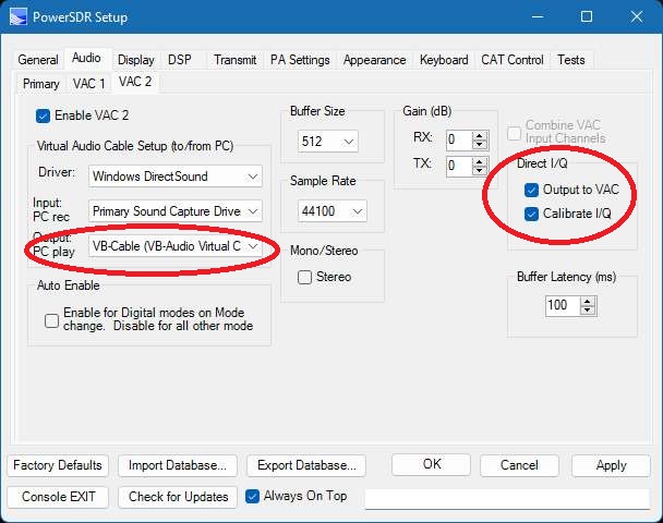
Below: SDC CW Skimmer with both RX1 and RX2 (Flex-5000) active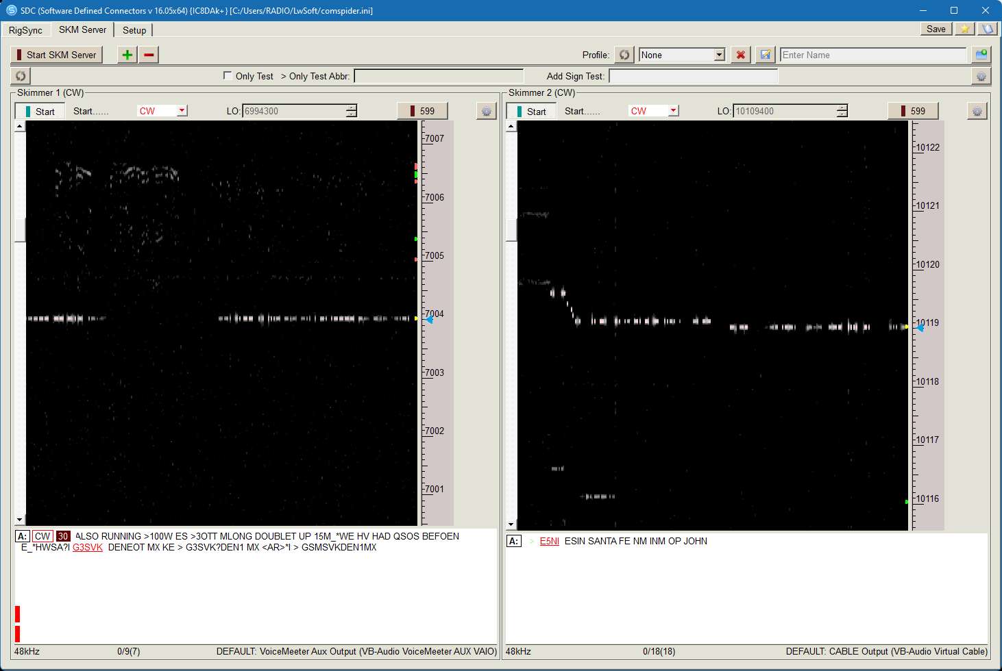
Below: SDC RigSync settings (baud to match PowerSDR. I use 115200). Note the 200mSec Poll time. Dont poll to fast since PowerSDR CAT is multiplexing many COM ports simultaneously
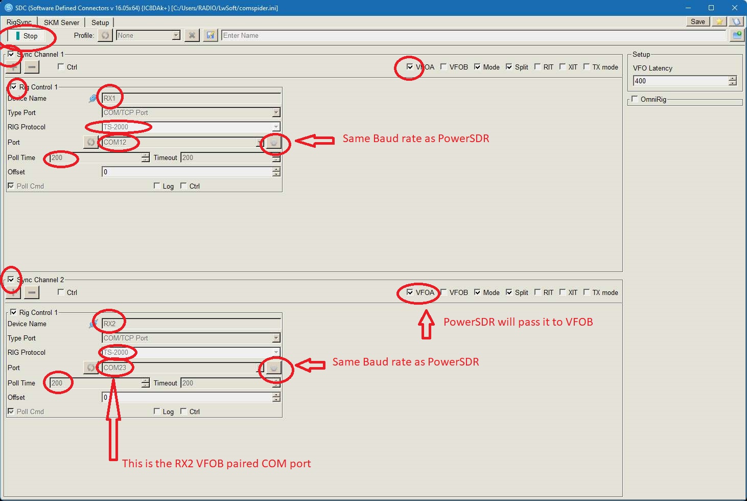
Below: SDC SKM Skimmer 1 Setup (RX1)
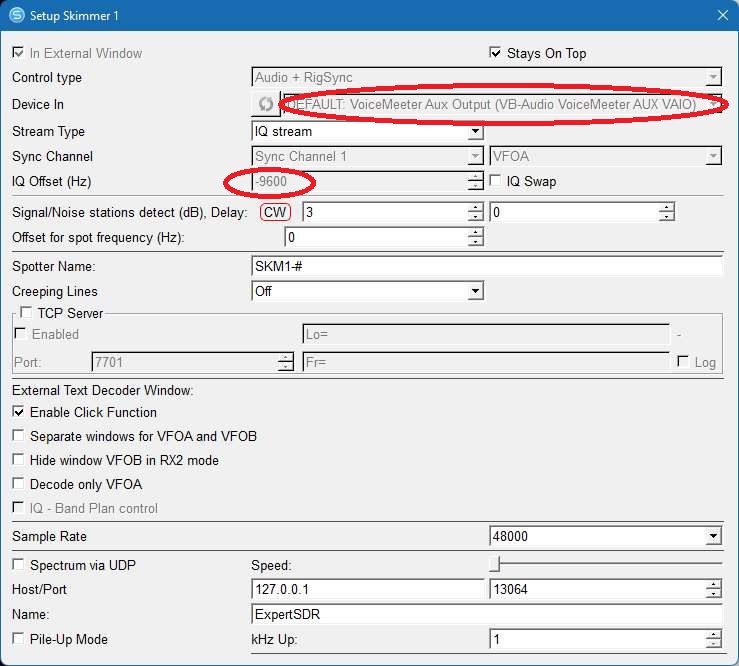
Below: SDC SKM Skimmer 2 Setup (RX2)
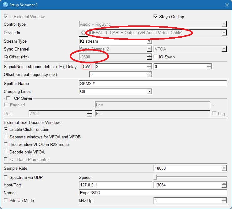
NOTE: For RX2 to work properly you must treat RX2 just like VFOA and Let PowerSDR "CAT RX2 VFOB" reroute to VFOB of your Flex-5000
------------------------------------------------------------------------------------------------------------------------------------------------
USAGE: Broadcast audio Communications, and text
DECODER: Dream.exe (free) Commercial DRM
(difficult to setup the codec and requires strong signals) Signals must be over S9 to work. Any interfearance on top of the 10khz signal will prevent decoding.
DREAM.EXE (Digital Audio decoder):Click here DReaM_v2.2.1_zefie1.1_xHE-AAC_FDK_Win8.1_x86 to Download the latest v2.2.1 (compiled with VS and QT5.12.0 and works with xHE-AAC support)
You must also install NPCAP (new version of WinPCap) from here: https://nmap.org/npcap/
The new version of DRM allows for lower bitrate requiring lower SNR
This compiled version was posted here: https://www.reddit.com/r/RTLSDR/comments/grp6m2/dream_v221_for_windows_with_xheaac_support/
MODE: PowerSDR Mode DRM, otherwise USB 10khz wide will work.
FREQ: DRM broadcast schedules from around the world: https://www.drm.org/?page_id=151
SOUND: Click to download audio file to hear what it sounds like
(LEFT: DREAM DRM program showing the radio Station. Make sure to adjust the PowerSDR audio RX output level so no RED appears in the vertical Green bar)
(RIGHT: 9k wide DRM signal. Note the AM broadcast directly to the right is the exact same broadcast in Analog AM)
(below: Click on View->Evaluation Dialog. This is the setup you should use. The SNR "MUST" be at least > 16 dB. Wait for all Green boxes, then you will hear audio over your PC speakers)
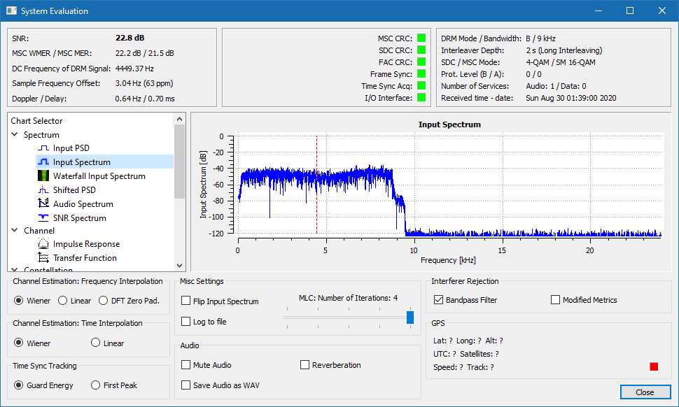
click on images to enlarge
------------------------------------------------------------------------------------------------------------------------------------------------
Amateur DRM
USAGE: Still image, file transfer, chat, QSL Communications
ENCODER/DECODER: EasyPal.exe (free). Signals must be over S9 to work well.
Files & Chat & Pictures: EasyPal with Hybrid TX is a free program for RX/TX Files/Photes in a 2.7khz bandwidth. Use E,2.4,HI,QAM4,24 for weak signals, QAM 16 only for strong signals. You can adjust the DRM speed to allow easier reception as a cost of transmission time.
Photos can take from 30 seconds to over 1 minute to send via HF DRM
NOTABLE: HYBRID TX: Easypal saves your File/Photo on an internet server, then sends only the link via HF DRM. Saves time and allows for a weaker signal since it only takes a few seconds to send the link via HF DRM. Allows a big group to exchange audio, photoes, etc without having to get email addresses or Skype names.
MODE: Band Mode (USB/LSB) 2.7khz wide (
Notable Waterfall image is a solid 2.7khz line with dark shadows or stips that appear to barber poll )
FREQ: 3.713, 7.173,14.233 Mhz
SOUND: Click to download audio file to hear what it sounds like
(left: signal as it appears in PowerSDR panfall) (right: signal as it appears in EasyPal)
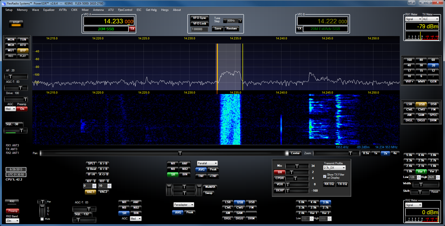
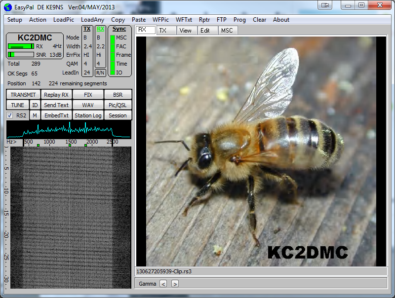
click on images to enlarge
------------------------------------------------------------------------------------------------------------------------------------------------
Amateur TV (SSTV)
USAGE: Analog Still images, QSL card Communications
ENCODER/DECODER: MMSSTV.exe (free) Need a strong signal to get a clear image.
Video: MMSSTV is a free program to decode 9 different Analog still TV images.
Download at:
https://hamsoft.ca/pages/mmsstv-yoniq.php
MODE: Band Mode (USB/LSB) 2.4khz wide (although the signal is typically around 1khz wide)
FREQ: 3.800, 14.230, 21.340, 28.680
SOUND: Click to download audio file to hear what it sounds like
left side: SSTV signal, right side: as it appears in MMSSTV
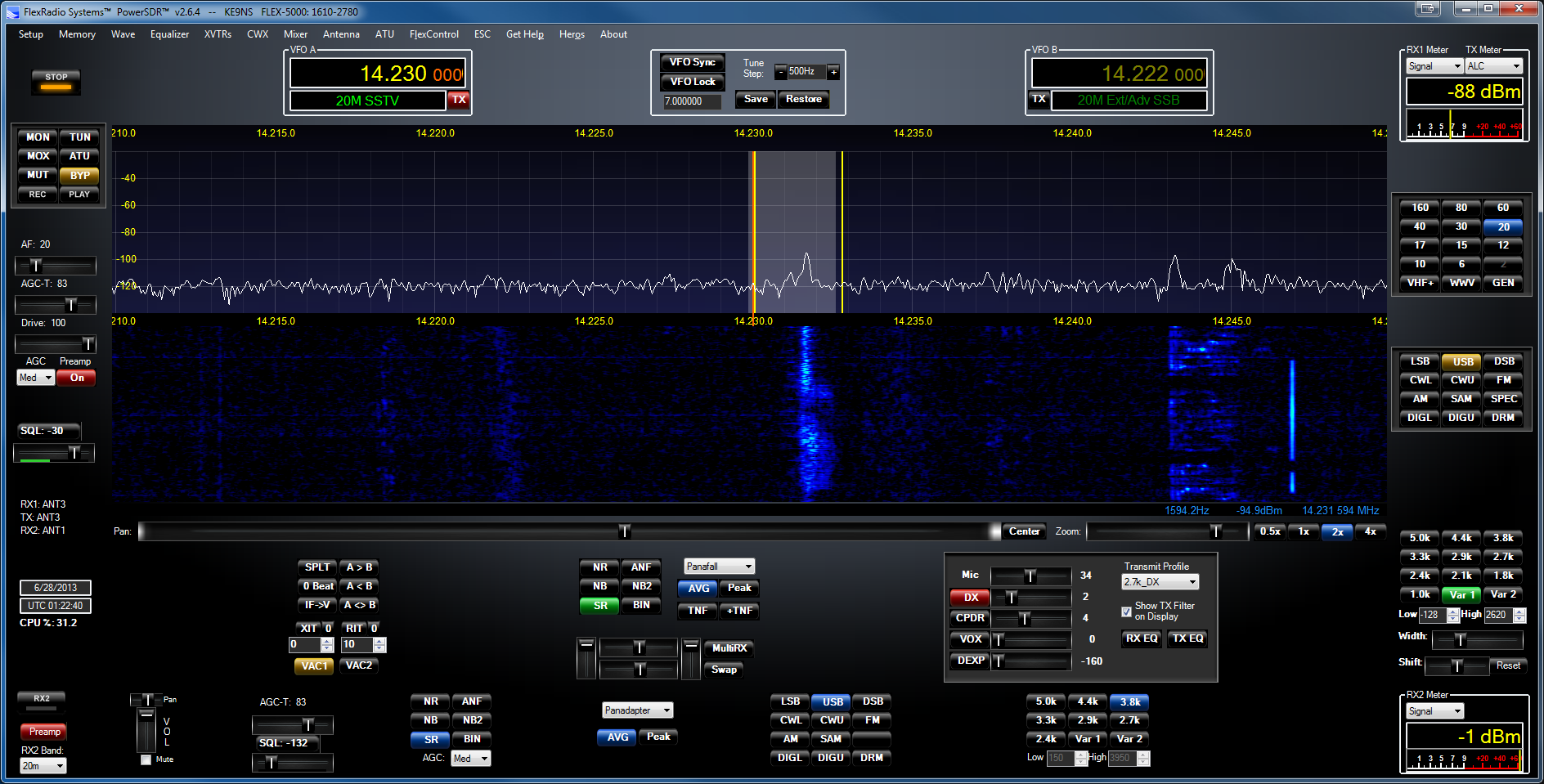
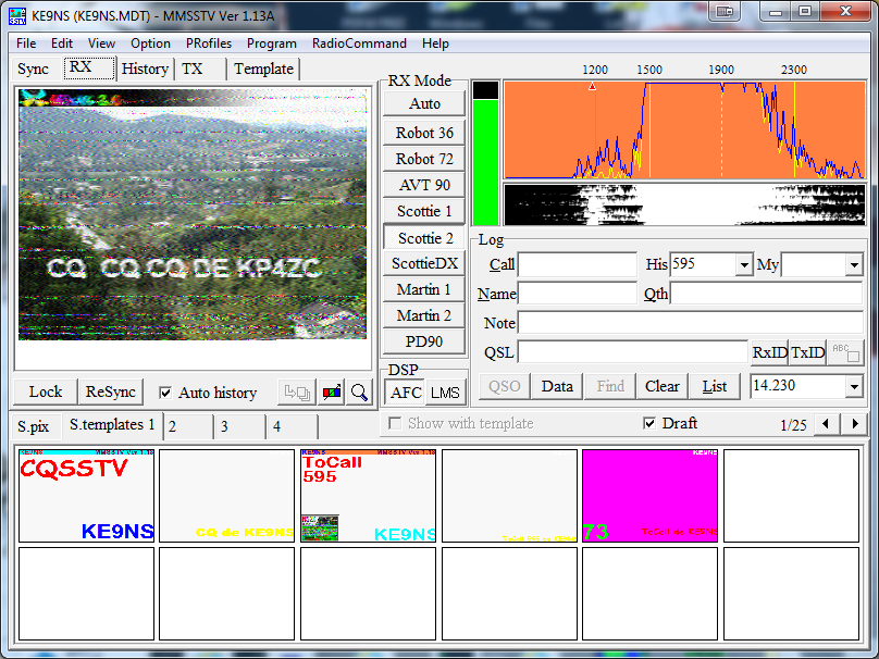
click on images to enlarge
------------------------------------------------------------------------------------------------------------------------------------------------
Amateur Digital Audio DV
USAGE: Digital Audio Communications
ENCODER/DECODER: FreeDV.exe (free). Need a strong signal to get audio (audio quality is sub-par due in part to vary narrow bandwidth)
MODE: Band mode (USB/LSB) 2.4khz wide (although the signal is only 1.6khz wide)
FREQ: Google FreeDV qso finder or look for the image below (14.236 mhz)
SOUND: Click to download audio file to hear what it sounds like (this is the 1600 mode)
(left: signal as it appears in PowerSDR panfall) (right: signal as it appears in freedv.exe)
click on images to enlarge
I dont use CAT, just a COM port pair (COM6 <> COM 7) as the PTT, but you could use VOX.
------------------------------------------------------------------------------------------------------------------------------------------------
Amateur Olivia
USAGE: Text based Communications
ENCODER/DECODER: Multipsk Olivia
MODE: USB 500hz wide
FREQ: CW portion of ham bands
SOUND: Click to download audio file to hear what it sounds like
(left: Multipsk) (right:PowerSDR)
------------------------------------------------------------------------------------------------------------------------------------------------
Amateur Contestia
USAGE: Text based Communications
ENCODER/DECODER: Multipsk or Fldigi
MODE: USB125hz, 250 hz or 500 hz or1khz
FREQ: CW portion of ham bands
SOUND: Click to download audio file to hear what it sounds like
------------------------------------------------------------------------------------------------------------------------------------------------
Amateur BPSK
USAGE: Text Communication
DECODER: Digipan
MODE: USB 4khz wide (each signal is 200hz wide , very narrow)
FREQ: CW portion of ham bands (3.580, )
SOUND: Click to download audio file to hear what it sounds like
(LEFT: multiple BPSK31 signals) (RIGHT: DigiPan decoder capable of tracking multiple signals (5 different types). The Green Flag indicates the conversation in the large window you are talking to. The other PSK streams are simply shown as a single line on the left side of the screen)
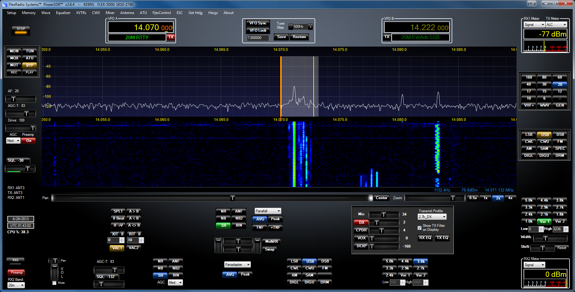
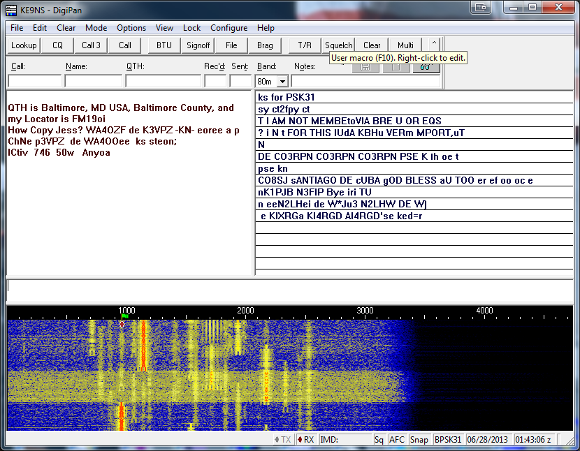
click on images to enlarge
------------------------------------------------------------------------------------------------------------------------------------------------
WWV or CHU Time/Date Decode
USAGE: Time/date
DECODER: PoweSDR T11 now decodes this. Clock (from the makers of multipsk). The free version will show you the correct time, but will not update your computers time.
MODE: AM
FREQ: WWV (AM mode) 2.5, 5, 10,15,20,25 mhz, CHU (ISB mode), and most otherTime signals
SOUND: WWV: Hidden 100 hz from the carrier are the Second's pulses that are either short or long second pulses, you can decode this into TIme & Date. CHU: Between 31st and the 39th second, transmitted in a FSK ( USB) transmits the Time/Date.
(Left: The Free CLOCK program, Right: WWV signal in AM mode)
If you want a free program to update your computers time (down to the second) download this file: Internet Time Update.exe
Just put it on your desktop and run it. you can set it up to update every hour. Windows 10 makes it difficult to update your time down to the second.
------------------------------------------------------------------------------------------------------------------------------------------------
Noaa Weather Fax
USAGE: Weather maps
DECODER: Sorcerer, MSCAN METEO, Fldigi, MixW2, Multipsk
MODE: USB (around 3.5khz wide)
FREQ: Varies (9.108, 6.3415, 4.3165 mhz)
SOUND: Click to download audio file to hear what it sounds like
(Left: The Free but not supported Sorcerer V1.01 with the Fax Decoder running, Right: HF Fax signal in the panfall, USB)
------------------------------------------------------------------------------------------------------------------------------------------------
NATO STANAG 4285
USAGE: NATO Communication
DECODER: Sorcerer, Sigmira, Multipsk
MODE: USB 4khz wide (signal is around 3.0khz wide)
FREQ: Varies (8.4785,8.701 mhz)
SOUND: Click to download audio file to hear what it sounds like
(Left: SIGMIRA program to decode STANAG 4285 signals)
You need to make sure the VAC1 out from the Flex is set as the default RECORD source for SIGMIRA to see it. 
------------------------------------------------------------------------------------------------------------------------------------------------
ALE (Automatic Link Establishment)
USAGE: Freq Scanner for sending/receiving short messages (for ham radio or Mars)
DECODER: ALE.exe (free), Mars-ALE.exe (free) You need to make sure the VAC1 out from the Flex is set as the default RECORD source for ALE to see it.
MODE: USB 2.4khz wide
FREQ: Google for listing
SOUND: Click to download audio file to hear what it sounds like
SETUP: PCALE.EXE has a FLEXRADIO Rig to allow control of your Flex via CAT commands. You may need to use the "Default" playback and Recording devices instead of VB-Audio Cables. PCALE appears to be very buggy, and doesnt appear to properly do SPLIT RX/TX operation.
(Left: ALE.exe program to decode MIL-STD-188-141A or 110 signals)
Notice the Vertical RED lines in the Tuning window when a 141A or 110 signal is present. 
------------------------------------------------------------------------------------------------------------------------------------------------
DSC (Digital Selective Calling) & Navtex
USAGE: Maritime messaging system
DECODER: YADD.exe (for DSC), NAVTEX.exe, Fldigi, Multipsk, (for Navtex)
MODE: USB 1.5 khz wide (NAVTEX: USB FSK 150 HZ shift, 100 Baud, CCIR476 character format)
FREQ: 2.1875, 4.2075, 6.312, 8.4145, 12.577, 16.8045
SOUND: Click to download audio file to hear what it sounds like
Shown below is the NAVTEX.EXE
Shown below is the YaDD (yet another DSC) which if Free. This has the DSC frequencies built in and allows you to receive Maritime Mobile Ship-to-shore messages.
Searchable list of Navtex stations:
https://www.ndblist.info/datamodes/NAVTEXvw2.3.zip
AM and HD AM broadcast Signals
Searchable list of HF ShortWave stations (including DRM):
https://www.ndblist.info/beacons/EIBIview30.zip or
https://www.eibispace.de/dx/EIBIview30.zip
EIBIview is a great free program for a list of Shortwave stations that are on-the-air NOW.
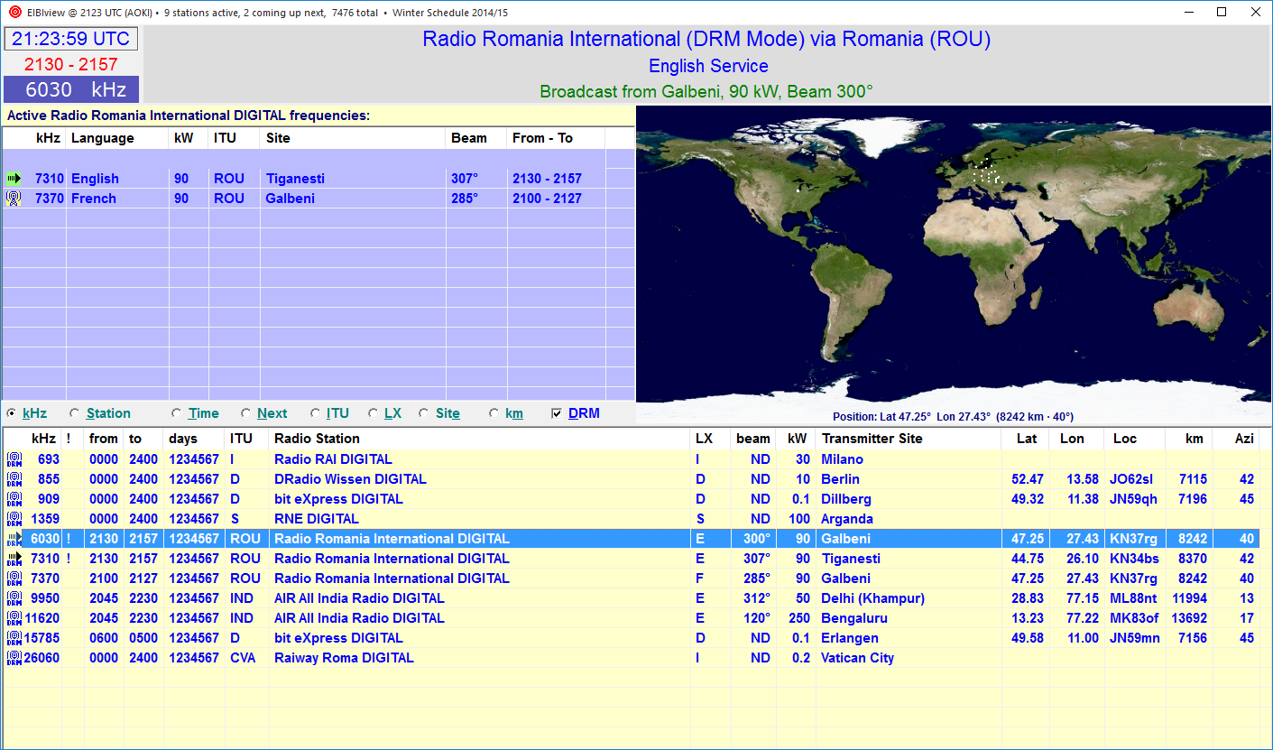
(LEFT IMAGE: Center: Clear Channel 20khz wide AM broadcast. Note the HD radio signal represented as [2] 5khz sideband digital signals.Right side is a traditional 12khz AM broadcast)
(RIGHT IMAGE: Center: AM broadcast with the LSB removed or
SSB AM)
Below is (Free) HD AM radio (iBiquity) as it appears in my car (MKZ) from the 0.670khz signal above (the HD circuitry decoding the [2] 5khz digital OFDM sideband signals). The digital signal is compressed using a proprietary version of mpeg-4-ACC, specifically to make sure nobody can legally write software to decode it.
Depending on how many sub-channels, the Digital sound quality can be very good.
Most FM HD stations have 1 or 2 sub-channels in addition to the HD version of the analog signal.
HD Radio is Free, but unfortunately not free to decode. The only decoder I have is built into my car.
FM HD is almost useless (unless your close to the transmitter) because the FCC limits the digital signal to 1 to 4 % of the Analog signal power output.
The HD Radio is designed to fall back to Analog if the digital is lost. The Analog and Digital signals are synchronized perfectly, so its seamless going back/forth. However sub-channels have no fall back.
Unknown or Undecodable(by me) Signals
USAGE: Stock trading data beamed from Northern Illinois to London, Munich, Mumbai, and Tokyo (used to try and beat underwater fiberoptic cables).
https://www.raft-tech.com/raft-articles/
i56578-swl.blogspot.com/2020/09/48-kbaud-oqpsk-unid-wideband.html
https://hcab14.blogspot.com/2019/11/update-on-oqpsk-signal-from-chicago.html
DECODER: Proprietary
MODE: 48khz WBHF, OQPSK
FREQ: Varies. 6.889mhz or around this location
Very consistant in strength and appearance.
USAGE: Maritime digital channel marker?
DECODER:?
MODE: 350 hz wide + CW ID?
FREQ: 8.420.5 mhz
SOUND: Click to download audio file to hear what it sounds like (ID: WLO)
Left: PowerSDR , Right: closeup view in Sigmira


USAGE: Technical Data Link (TDL)(Fast HF Automatic Link) Link-11
DECODER: Someone please suggest a free decoder (if available)
MODE: PSK +/- 3khz DSB, ISB, or SSB. Link-11, STANAG 5511, TADIL
FREQ: center: 5.430.6 mhz
SOUND: Click to download audio file to hear what it sounds like
Technical: https://en.wikipedia.org/wiki/Tactical_Data_Link
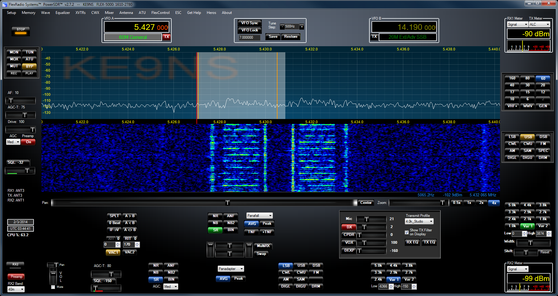
USAGE: ?
DECODER: ?
MODE: 20khz wide Possibly British Pluto II radar ?
FREQ: 11.465.5 mhz & 8.300 mhz
SOUND: Click to download audio file to hear what it sounds like
Right side of display: standard shortwave AM broadcast, but note the the 2 sideband peaks???)
USAGE: Ocean Study?
DECODER: ?
MODE: 80khz wide Possibly CODAR radar?
FREQ: 12.530 mhz - 12.612mhz
SOUND: Click to download audio file to hear what it sounds like (only +/- 10khz of it)
When it quits, it stays off for 10 minutes, then comes back on. Note the other signals its currently interfering with)
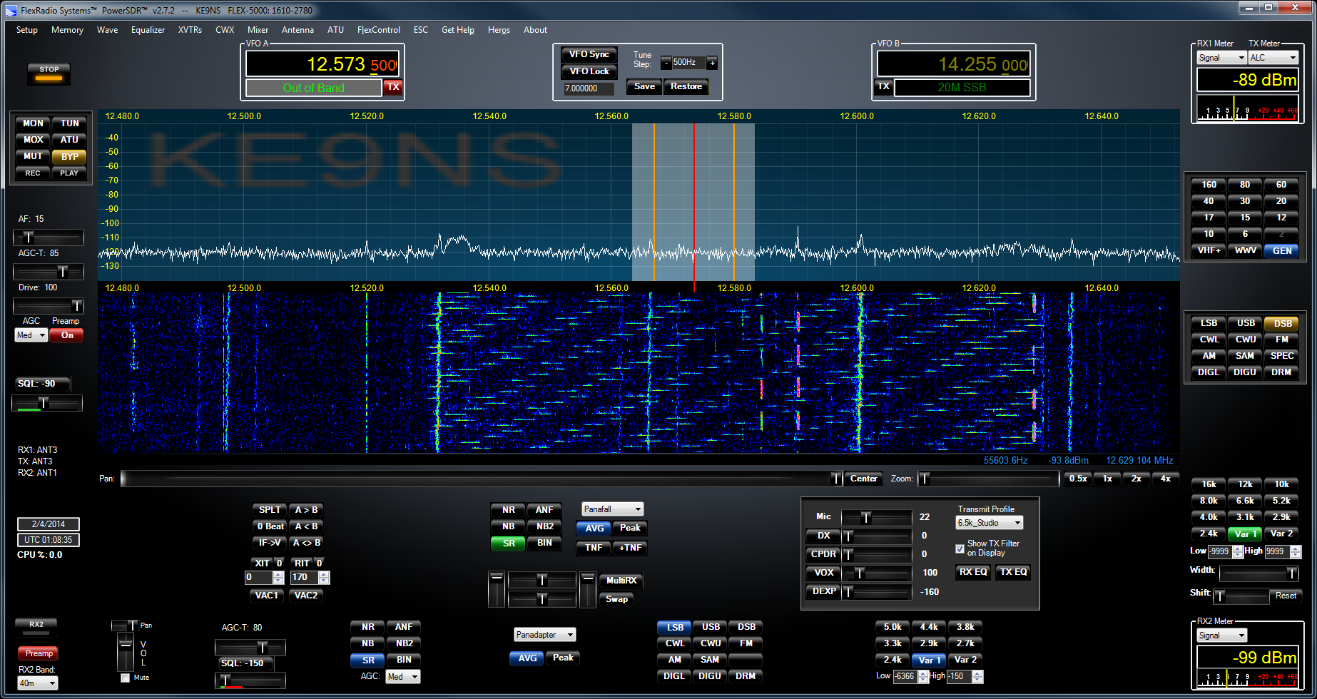
click on images to enlarge
USAGE: ?
DECODER:?
MODE:? khz wide Possibly Link11 SSB
FREQ: 8.304 mhz
SOUND:
(LEFT: 10 pulses than a long data transmission, repeat)

USAGE:?
DECODER: ?
MODE:8 khz wide Radar?
FREQ: 12.040 mhz
SOUND:
(RIGHT: Data burst, then randomly another but sound different. Sound faster or slower)
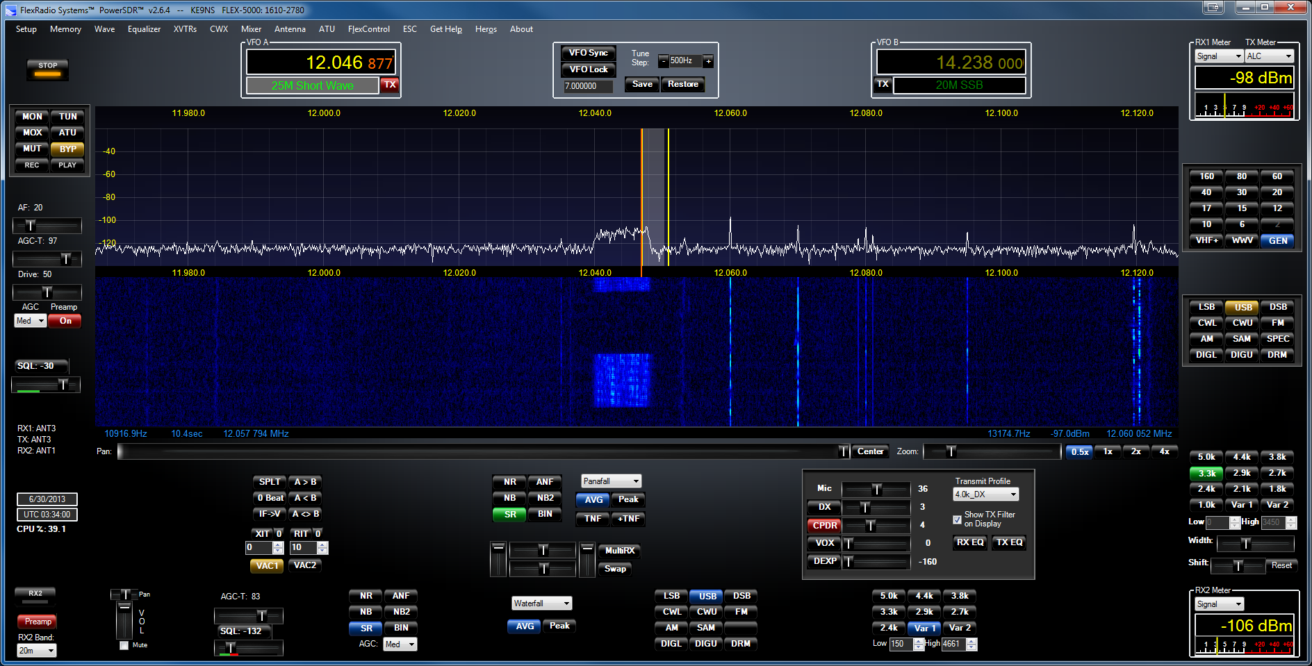
Filters for (BCB) AM Broadcast Band Interference
Even though the Flex-5000 has 11 sets of 11th order (LP) Low Pass band filters (1 set for every Amateur band), It doesnt have a AM Broadcast band Filter (BCB preselector). AM BCB Interference shows up on your Flex radio as an increased noise floor, or you may hear AM broadcast stations on Ham bands and see carrier spikes as well.
Flex-5000: You can place an external "RX only" filter inline. Get yourself an AM broadcast notch filter if you want to hear Marine and the LF/MF ham bands, OR and AM broadcast HPF (easier to find) if you dont care to hear anything in the MF/LF bands. Place the filter in the RX1 In - Out Loop BNC jacks.
Flex-1500/Flex-3000: You can place an external TX/RX (100 watt capable) filter directly inline with the Antenna output as either a AM broadcast Notch filter or AM broadcast HPF (this is easier to find)
I live 5 miles away from a large clear-channel AM transmitter. Certain times of night it shows up across 160m thru 60m.
My Clifton Labs BC notch type filter completely notches out the AM Broadcast band (S9+40db signals reduced to -120db)
(Shown: Clifton Labs Z10020B is a true notch filter 540khz thru 1700khz)
The B is the 160m option
DX Engineering now sells the Z10020
Clifton no longer makes my box, but they do make a seperate board / box combo (below):
DX Engineering Clifton Laboratories Z10020 AM Band Filter Module DXE-Z10020-PM
DX Engineering Dual Module Chassis DXE-DMC-2
For just a HPF there is the DLW-FL1718 for a 200w rated inline filter
or https://kf7p.com/KF7P/Morgan_Filters.html ( M-402X). But you will lose everything below 160m
Amateur 630m Band (472khz to 479khz)
The Flex-3000 will output 100watts (actually 130watts but I would limit yourself to 100watts) on 630m, and the SWR / Power meters appear to function correctly, but the calibration is way off this far below 160m, so the DRIVE level will be way off in relation to actual output. And you will need an external 630m LPF that can handle 100 watts.
The Flex-5000 does not appear to be able to transmit more than a watt on 630m (in Extended mode). Power tappers off as you dip below 160m, so there is nothing remaining by the time you reach the AM BC band.
FILTERS:
The Flex-1500,3000,5000 have no filtering below the 160m band (RX or TX).
The 160m LPF is selected when below 2mhz.
This means you will normally see many overload signals from the AM broadcast and 160m bands.
IMPORTANT: You will need to add a LPF filter designed for the 630m band for both RX/TX (100 watt capable).
This will not only filter your Transmit harmonics, but also the AM broadcast and 160m signal overload that ends up flooding the Panadapter.
IMPORTANT: When transmitting on 630m you will want to trim your TX profile low freq and high freq as narrow as possible to avoid transmit issues. (Example: low = 600hz, high = 2200hz)
You will also need to be running in "Extended" mode.
FCC requires you first get permission, from your local power company, before transmitting.
https://www.arrl.org/news/fcc-opens-630-and-2200-meter-bands-stations-must-notify-utc-before-operating
Or the direct application here:
https://utc.org/plc-database-amateur-notification-process/
This is the response email I received giving me authorization to operate 630m band
See http://www.472khz.org/ for lots of info on 630m band.
1/14/22: Homemade 630m LPF for RX and TX operation
(using parts I had around and vk6ysf for ref):
(2) ~16uH (16 turns of 14awg transformer wire around a 502T3003E2A toriod), and 562 (5600pf) 1kv caps (2 in parallel for the center, and 1 on each end to ground):
You can see its 44db down
at 1.6mhz. So when combined with my AM BC Notch Filter, the built in 160m LPF in the Flex radio itself, and my 630M LPF, this should clean up the RX and TX
You would be advised to make a LPF that is tighter with a cut-off at the AM Broadcast band.
I put my 100 watt capable TX/RX 630m LPF into an aluminum project box (still waiting for my SO-239 panel mount connectors):
Bucket Variometer loading coil for my G5RV in GMV configuration:
5gal paint bucket (29 turns of 14awg above and below the 1" PVC for max 600uH with 4 taps on the lower portion every 3 turns), (25 turns above and below the center of a 3" PVC pipe for 96uH of inductive buck). I can vary the inductance from ~200uH to ~600uH. 472khz.org says I should need around 400uH as a loading coil at the base of my G5RV converted to a T with ground radials.
(below) Attached the Bucket Variometer to my G5RV (shorting the PL259 as it connects to the ladder line). And utilizing the ground radials and ground rods I already had in place under the G5RV for my 160m switch.
Attached the NanoVNA to the coax that would connect to my Radio. Easy to adjust the inductance by turning the end of the PVC pipe. With the LPF inline, I can tune SWR for 2:1 on 630m.
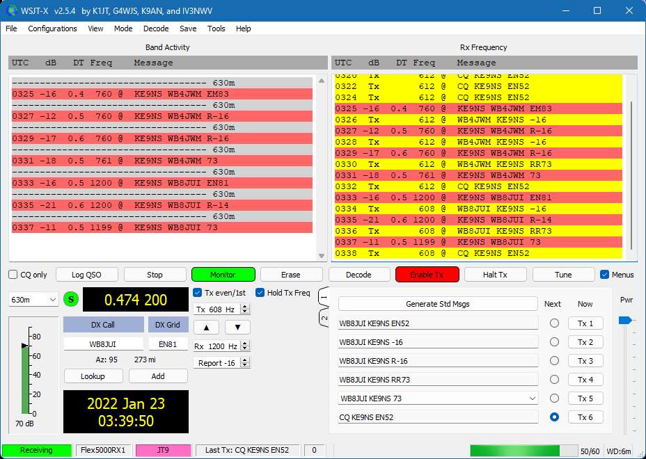
First 2 contacts running JT9 on 630m at 50watts from my Flex-3000 thru a LPF and my G5RV (with Bucket Varimeter and ground radials).
Just found out that FST4-60sec interval is the more popular mode. FST4-120sec is for DX
Typically you will hear "WSPR" and "FTS4-60sec" signals around 474.2khz (+800hz to +1400hz). Download wsjt-x to decode and transmit.The FTS4-60 signal appears slightly wider than the WSPR signal. WSPR appears almost as a straight line.
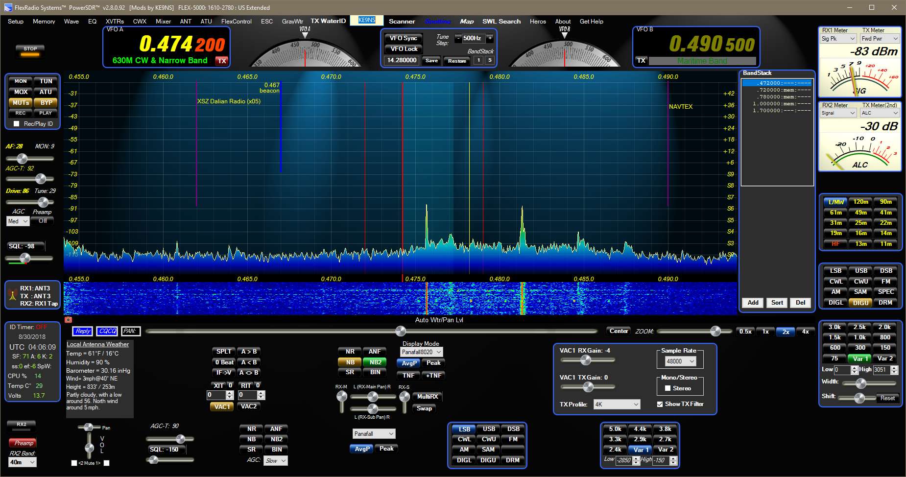
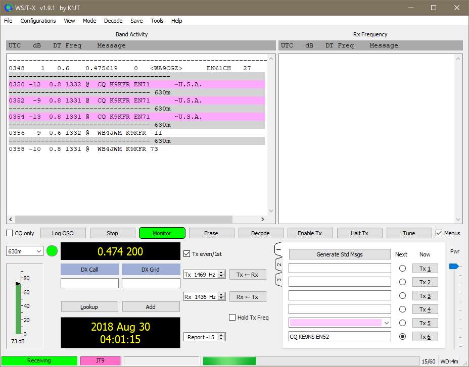
(above) WSJT-x showing both wspr and jt9 decodes, manually switching modes myself.
(below) wsjt-x waterfall showing jt9 on the left side, and wspr on right
side
Since 630m requires a long antenna, you will typically need a very large loading coil at the base of the antenna to tune the SWR flat (search 630m variometer in google) and keep the losses down. Note: These coils can generate lethal voltages with only a few watts on transmit.
Receiver Birdies (Panadapter Bridies)
The PowerSDR Panadapter exposes a whole set of new issues to deal with in radio. When you open up the Panfall to 192khz, and adjust the waterfall color levels, you will see many signals across all parts of the HF band. Sometimes issues crop up and you start to see things that dont add up. All Radio's have their Birdies, its just on that on the Flex (with its great sensitivity) its disconserting to see them all at 1 time.
If you believe the signal you are seeing might be a data transmission try "Artemis Radio signal detection" program you can run from your PC.
Download at: https://aresvalley.com/artemis/
Click to download a copy of "US Navy Noise Handbook"
1) You see spikes appear and dont move as you scroll frequencies.
This could be a software issue in PowerSDR, or your PC or Firewire connection slowing down causing DSP conversion issues. Check PC services running in the background. Reset the software or your entire computer.
Or this could be a birdie cause by the DSP hardware/software
2) You see signals across the Panadapter, but upon inspection determine that they are real signals but repeating at intervals across the spectrum.
This is frontend overload. You may need to add a Broadcast band filter to RX1
This can also be Switchmode or IF hash coming from sources all over your house (see below)
3) You see the waterfall noise level changes or jumps.
This could be when you switch between bands, and because your antenna is designed for certain bands, its efficiency on any band will change.
When you leave a Ham band for a General Shortwave band, you dont have the same hardware filtering.
or the PowerSDR or PC has issues and you may need to reset.
Run remote desktop on your Laptop (running on battery) and go around your house and garage. Unplug everything and check the Panadapter.
The worst offender for noise/Birdie issues is the "Switchmode" power supply. Some can be so bad, they can be in your neighbors house.
1) Your Desktop PC switchmode will generate noise: Be carefull when putting the Computer to SLEEP, this can create noise throught the HF band, more than simply turning the PC off or leaving it ON. I think its becuase the PC goes into LOW POWER mode and the switchmode is designed for larger loads.
2) Your Desktop PC CLOCK will generate noise: Check
your bios settings for PC CLOCK "SPREAD SPECTRUM" try setting this both ways.
3)
Your Laptop inline power supply can be a big noise generator. Sometimes its worse when its plugged in, but your laptop is in lowpower mode.
4) Your Flat Screen TV: unplug it.
5) Light Dimmer
6) Garage Door Opener (the receiver circuit on the opener itself).
7) Your Cordless Drill battery Charger
8) Microwave oven (usually interferes with TV).
9)
DSL or UVerse or Cable
10) BPL
or HomePlug (Internet data over your home's AC wiring (Dish Network boxes have this feature)
Some of this may be removed by installing a CLAMP-ON Ferrite Bead designed to Choke HF
Changing your Flex Radio TURF (Region) & MARS
Look at the top line of v2.8 PowerSDR. It will contain the Model#, Serial#, and Turf "Region" of your Flex Radio.
Current list of "Regions":
US = USA, CA, ROW
UK
Europe = Germany, European Union, IARU1
UK_Plus = UK+ (adds 60m band)
Italy
Norway = Norway, Czech Rep.
Denmark
Latvia
Slovakia = Slovakia, Malta
Bulgaria
Greece
Hungary
Belgium
France
Russia
Sweden
IARU3 = China, Australia, New Zealand
Japan
Italy_Plus = Italy+ (40m band)
ES_CH_FIN = Spain, Switzerland, Finland
Netherlands
EU_Travel
Luxembourg
IARU2 = Central & South America
Australia
China
_______________________________________
The TURF region determines your Band Privileges (where you can transmit)
The TURF region is programmed into the Radio's EEPROM
Once you update the TURF Region of your Flex Radio, cycle power,
Run PowerSDR
setup->General->Options. Click on "Update BandText" button
This will update the "Band Text" that appears just below VFO-A and VFO-B
to match your "Region"
NOTE: If you just added 60m band transmit to your Flex and you run into trouble, search this webpage for:
60m update to IARU Region 1
NOTE: Firmware updates provided in PowerSDR software will NOT disable your "Extended" or MARS operation.
So dont worry.
_______________________________________
MARS / SHARES operation (Extended operation)
The Flex-1500, Flex-3000, Flex-5000 can be made to operate in "Extended" or MARS/SHARES mode.
SHARES=SHared RESources High Frequency Radio Program
(see https://www.cisa.gov/shared-resources-shares-high-frequency-hf-radio-program for details)
MARS=Military Auxiliary Radio System (and AFMARS Air Force MARS)
(see https://www.mars.af.mil/ for details)
NOTE: Firmware updates provided in PowerSDR software will NOT disable your "Extended" or MARS operation.
So dont worry.
If your Flex Radio has MARS (Extended) operation enabled, the top line of v2.8 PowerSDR will not only show your TURF Region but also show the word "Extended"
The Flex-5000a links to a Windows PC via a 400Mb/s IEEE1394 FireWire cable
PowerSDR Ver 2.7.2 SVN 5123 (Rev L) (in Program Files(x86) folder)
FlexRadio Ver 4.1.3 (in Program Files folder)
Flex-5000 Firmware Ver 2.1.3.9 (under Program Data folder)
Flex 5000 Specs (based on what I can determine):
ARM7TDMI 32bit processor, AD9511 master clock (500 mhz), AD9959 10bit 500msps DDS for generating the LO (seperate outputs for RX and TX), AK53394A 192khz A/D for RX (IF), CS42448 for A/D & D/A audio in/out, 74CBT3253PW used as a digital mixer (1 for TX and 1 for RX).
TX output signal is created by mixing the D/A CS42448 audio thru a 74CBT3253PW mixer with the AD9959 LO
RX input is determined by mixing the AD9959 LO thru a second 74CBT3253PW mixer with the Antenna circuit, then sending the I/Q signals to the AK5394A for 192khz bandwidth
Where the Flex 6000 series and Hermes SDR's use an A/D capable of directly sampling RF energy (so you can view huge sections of RF at one time), the Flex 5000 uses a LO to mix down the RF directly down to a192khz window.
Newer SDR's (like the Flex-6000 series) perform DSP Internally, where prior generation SDR radios required a PC for the DSP.
While the 5000 is no longer state-of-the-art, it still remains a top receiver (see https://www.sherweng.com/table.html)
| Locations of fellow PowerSDR users around the world, and those currently viewing this page: |
